T1N Sprinter Differential & Driveline - Rear Axle
Torque Chart
| Description | Nm | Ft. Lbs. | In. Lbs. |
|---|---|---|---|
| Drain Plug | 100 | 74 | --- |
| Fill Plug | 100 | 74 | --- |
| Differential Cover Bolts | 65 | 48 | --- |
| Ring Gear Bolts | 180 | 133 | --- |
| Differential Bearing Cap Bolts | 70 | 52 | --- |
| Differential Case Bolts | 45 | 33 | --- |
| Axle Bearing Cap Bolts | 72 | 53 | --- |
| Axle Grooved Nut | 500 | 369 | --- |
| Axle Shaft Hub Nut | 65 | 48 | --- |
| Hub Inner Nut | 300 | 221 | --- |
| Hub Outer Nut | 250 | 184 | --- |
| Follow service procedure for torque sequence. | |||
AXLE SPECIFICATIONS
| Description | Specification |
|---|---|
| Axle Ratio | 3.73, 4.11 |
| Ring Gear Diameter | 216 mm (8.5 in.) |
| Ring Gear Backlash | 0.10-0.15 mm (0.004-0.006 in.) |
| Pinion Torque to Rotate | 2.5-3.0 N·m (22-26 in. lbs.) |
| Differential Bearing Preload | 0.16 mm (0.006 in.) |
| SRW Differential Torque to Rotate | 20-40 N·m (15-30 ft. lbs.) |
Special Tools
Special Tool Cross-Reference Chart
| MB Tool # | Miller Tool # | Description. | |
|---|---|---|---|
| N/A | C-293-PA | PULLER/PRESS |
|
| N/A | C-293-37 | ADAPTERS |
|
| N/A | C-293-47 | ADAPTERS |
|
| N/A | C-293-3 | ADAPTER PLUG |
|
| N/A | C-3281 | HOLDER |
|
| N/A | C-4310 | INSTALLER |
|
| N/A | D-103 | REMOVER |
|
| N/A | MB-998805 | INSTALLER |

|
| N/A | 8617 | INSTALLER |
|
| N/A | 8992 | FLANGE PULLER |
|
| N/A | 9084 | REMOVER |
|
| N/A | 9275 | INSTALLER |
|
| 460 589 15 15 00 | 9276 | INSTALLER |
|
| 741 589 00 35 00 | 9277 | PLATE |
|
| 741 589 01 15 00 | 9278 | INSTALLER |
|
| 460 589 01 07 00 | 9279 | WRENCH |
|
| 309 589 01 07 00 | 9290 | WRENCH |
|
| 389 589 02 15 00 | 9291 | INSTALLER |
|
| N/A | 9317 | SPREADER ADAPTERS |
|
| N/A | 9523 | INSTALLER |
|
| N/A | 9548 | INSTALLER |
|
| 460 589 11 15 00 | 9744 | TORQUE TOOL |
|
| N/A | 9571 | ARBOR DISC |
|
| N/A | D-115-2A | SCOOTER BLOCK |
|
| N/A | 6448A | INSTALLER |
|
| N/A | 9524 | DIAL INDICATOR |
|
| N/A | 9572 | PINION BLOCK |
|
DIAGNOSIS AND TESTING - REAR AXLE
GEAR NOISE
Axle gear noise can be caused by insufficient lubricant, incorrect backlash, incorrect pinion depth, tooth contact, worn/damaged gears, or the carrier housing not having the proper offset and squareness.
Gear noise usually happens at a specific speed range. The noise can also occur during a specific type of driving condition. These conditions are acceleration, deceleration, coast, or constant load.
When road testing, first warm-up the axle fluid by driving the vehicle at least 5 miles and then accelerate the vehicle to the speed range where the noise is the greatest. Shift out-of-gear and coast through the peak-noise range. If the noise stops or changes greatly:
- Check for insufficient lubricant.
- Incorrect ring gear backlash.
- Gear damage.
Differential side gears and pinions can be checked by turning the vehicle. They usually do not cause noise during straight-ahead driving when the gears are unloaded. The side gears are loaded during vehicle turns. A worn pinion shaft can also cause a snapping or a knocking noise.
BEARING NOISE
The axle shaft, differential and pinion bearings can all produce noise when worn or damaged. Bearing noise can be either a whining, or a growling sound.
Pinion bearings have a constant-pitch noise. This noise changes only with vehicle speed. Pinion bearing noise will be higher pitched because it rotates at a faster rate. Drive the vehicle and load the differential. If bearing noise occurs, the rear pinion bearing is the source of the noise. If the bearing noise is heard during a coast, the front pinion bearing is the source.
Differential bearings usually produce a low pitch noise. Differential bearing noise is similar to pinion bearing noise. The pitch of differential bearing noise is also constant and varies only with vehicle speed.
Axle shaft bearings produce noise and vibration when worn or damaged. The noise generally changes when the bearings are loaded. Road test the vehicle. Turn the vehicle sharply to the left and to the right. This will load the bearings and change the noise level. Where axle bearing damage is slight, the noise is usually not noticeable at speeds above 30 mph.
LOW SPEED KNOCK
Low speed knock is generally caused by a worn U-joint or by worn side-gear thrust washers. A worn pinion shaft bore will also cause a low speed knock.
VIBRATION
Vibration at the rear of the vehicle is usually caused by a:
- Damaged drive shaft
- Missing drive shaft balance weight(s).
- Worn or out-of-balance wheels.
- Loose wheel lug nuts
- Worn U-joint(s).
- Loose/broken springs.
- Damaged axle shaft bearing(s).
- Loose pinion gear nut.
- Excessive pinion yoke run out.
- Bent axle shaft(s).
Check for loose or damaged front-end components or engine/transmission mounts. These components can contribute to what appears to be a rearend vibration. Do not overlook engine accessories, brackets and drive belts.
DRIVELINE SNAP
A snap or clunk noise when the vehicle is shifted into gear (or the clutch engaged), can be caused by:
- High engine idle speed.
- Transmission shift operation.
- Loose engine/transmission/transfer case mounts.
- Worn U-joints
- Loose spring mounts.
- Loose pinion gear nut and yoke.
- Excessive ring gear backlash.
- Excessive side gear to case clearance
The source of a snap or a clunk noise can be determined with the assistance of a helper. Raise the vehicle on a hoist with the wheels free to rotate. Instruct the helper to shift the transmission into gear. Listen for the noise, a mechanics stethoscope is helpful in isolating the source of a noise.
Standard Procedure Drain And Fill
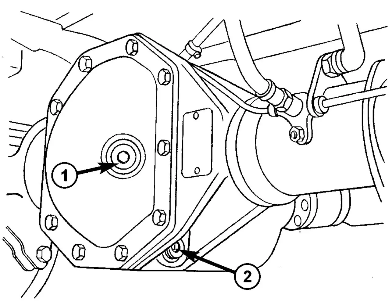
Fig. 1 FILL PLUG
- Clean area around oil fill plug and drain plug.
- Remove oil drain plug (2) and drain oil (Fig. 1).
- Install oil drain plug and tighten to N·m 100 (74 ft. lbs.).
- Remove oil fill plug (1) and fill housing up to bottom edge of oil fill hole (Fig. 1).
- Install oil fill plug and tighten to N·m 100 (74 ft. lbs.).
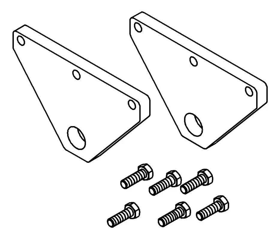
Rear Axle Removal
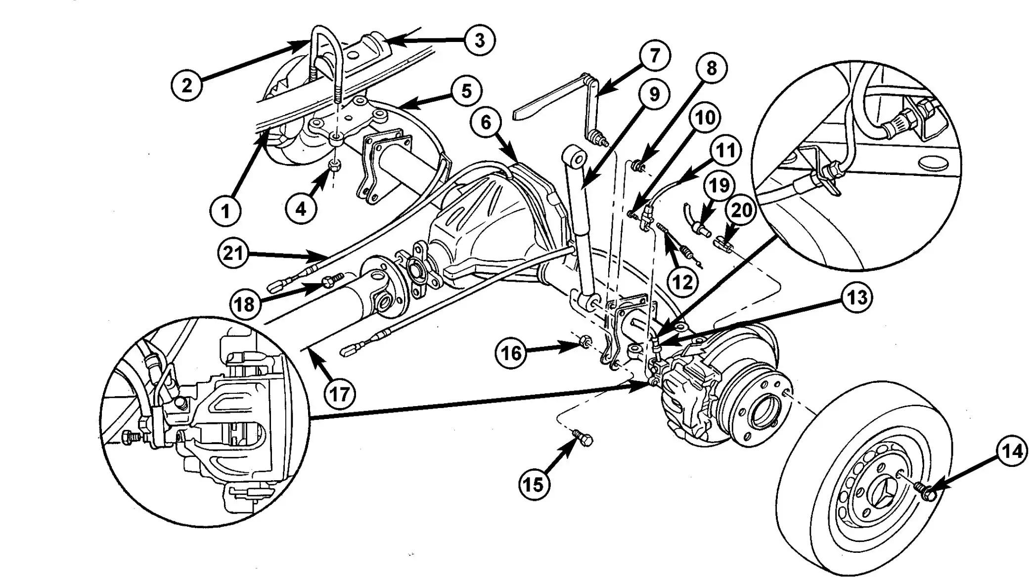
Fig. 2 SINGLE REAR WHEEL AXLE
- 1 - REAR SPRING
- 2 - U-BRACKET
- 3 - PLATE
- 4 - NUT
- 5 - BRAKE CABLE
- 6 - REAR AXLE
- 7 - ABL LEVER
- 8 - NUT
- 9 - SHOCK ABSORBER
- 10 - BOLT
- 11 - WEAR INDICATOR CABLE
- 12 - WEAR INDICATOR CONNECTOR
- 13 - BRAKE HOSE
- 14 - WHEEL BOLT
- 15 - BOLT
- 16 - NUT
- 17 - PROPELLER SHAFT
- 18 - BOLT
- 19 - ABS SENSOR
- 20 - SENSOR BUSHING
- 21 - VENT LINE
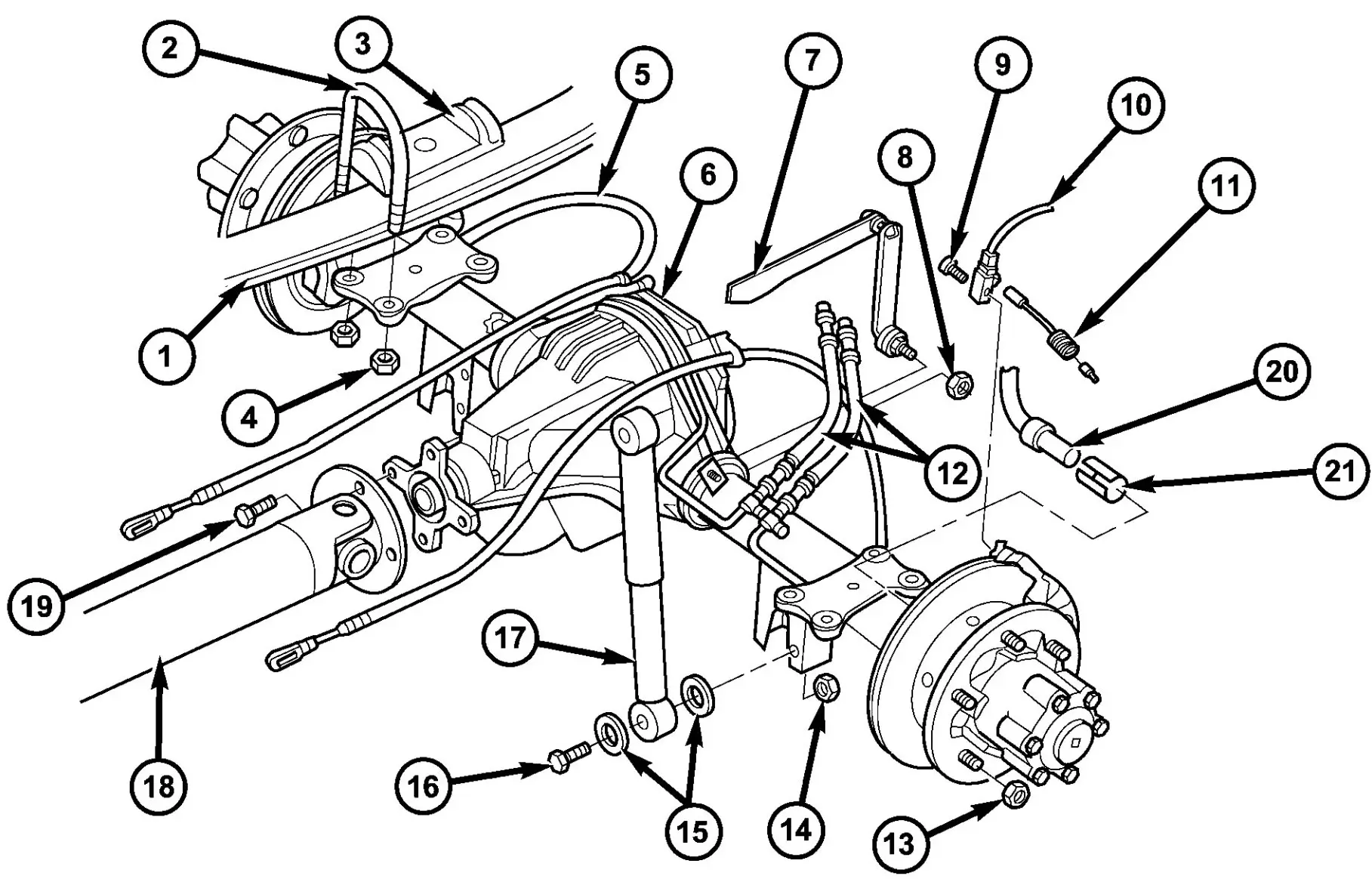
Fig. 3 DUAL REAR WHEEL AXLE
- 1 - SPRING
- 2 - SPRING SHACKLE
- 3 - PLATE
- 4 - COLLAR NUT
- 5 - BRAKE CABLE
- 6 - REAR AXLE
- 7 - ABL LEVER
- 8 - NUT
- 9 - BOLT
- 10 - WEAR INDICATOR CABLE
- 11 - WEAR INDICATOR CONNECTOR
- 12 - BRAKE HOSE
- 13 - LUG NUT
- 14 - NUT
- 15 - WASHER
- 16 - BOLT
- 17 - SHOCK ABSORBER
- 18 - PROPELLER SHAFT
- 19 - BOLT
- 20 - ABS SENSOR
- 21 - SENSOR BUSHING
- Raise and support the vehicle.
- Position a suitable lifting device under the axle and secure axle to a device.
- Remove wheels and tires.
- Unplug wear indicator cable (Fig. 2) and (Fig. 3).
- Detach cable connector for brake pad wear indicator.
- Remove ABS sensor and clamp bushing from mounting bore.
- Remove cable ties from the park brake cables. Release connection cable of brake pad wear indicator and ABS sensor cable up to the relay unit of the parking brake.
- Remove brake cables.
- Remove hand brake cable at relay unit.
- Remove bracket for brake cables at rear axle tube.
- Remove stabilizer bar from axle brackets.
- Remove shock absorber bolts from the rear axle.
- Remove ALB lever from rear axle bracket.
- Pull the vent line of the rear axle out of the frame.
- Remove propeller shaft.
- Remove brake calipers.
- Remove U-brackets and plates (Fig. 2) and (Fig. 3).
- Remove the axle from the vehicle.
Rear Axle Installation
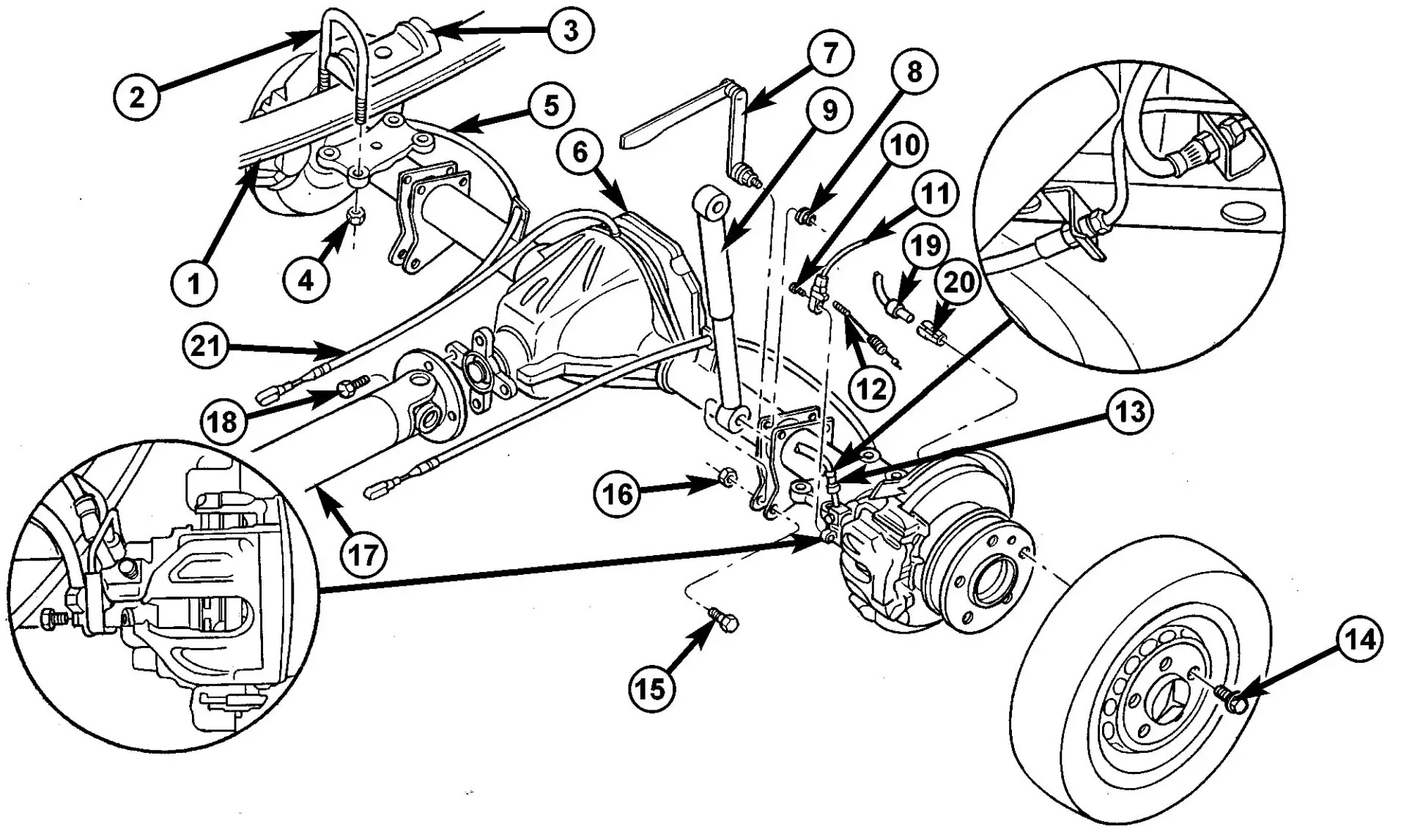
Fig. 4 SINGLE REAR WHEEL AXLE
- 1 - REAR SPRING
- 2 - U-BRACKET
- 3 - PLATE
- 4 - NUT
- 5 - BRAKE CABLE
- 6 - REAR AXLE
- 7 - ABL LEVER
- 8 - NUT
- 9 - SHOCK ABSORBER
- 10 - BOLT
- 11 - WEAR INDICATOR CABLE
- 12 - WEAR INDICATOR CONNECTOR
- 13 - BRAKE HOSE
- 14 - WHEEL BOLT
- 15 - BOLT
- 16 - NUT
- 17 - PROPELLER SHAFT
- 18 - BOLT
- 19 - ABS SENSOR
- 20 - SENSOR BUSHING
- 21 - VENT LINE

Fig. 5 DUAL REAR WHEEL AXLE
- 1 - SPRING
- 2 - SPRING SHACKLE
- 3 - PLATE
- 4 - COLLAR NUT
- 5 - BRAKE CABLE
- 6 - REAR AXLE
- 7 - ABL LEVER
- 8 - NUT
- 9 - BOLT
- 10 - WEAR INDICATOR CABLE
- 11 - WEAR INDICATOR CONNECTOR
- 12 - BRAKE HOSE
- 13 - LUG NUT
- 14 - NUT
- 15 - WASHER
- 16 - BOLT
- 17 - SHOCK ABSORBER
- 18 - PROPELLER SHAFT
- 19 - BOLT
- 20 - ABS SENSOR
- 21 - SENSOR BUSHING
- Raise axle into position.
- Install plates and U-brackets (Fig. 4) and (Fig. 5) with new nuts. Tighten nuts to 170 N·m (125 ft. lbs.).
- Install propeller shaft and tighten bolts to 70 N·m (52 ft. lbs.).
- Install ALB lever to axle bracket and tighten new nut 34 N·m (46 ft. lbs.).
- Install shock absorbers to rear axle and tighten bolts to:
- M12 x 1.5 Bolt - 70 N·m (52 ft. lbs.)
- M14 x 1.5 Bolt - 110 N·m (81 ft. lbs.)
- Install stabilizer bar to axle and tighten bolts to:
- SRW Axle - 25 N·m (18 ft. lbs.)
- DRW Axle - 70 N·m (52 ft. lbs.)
- Install calipers with adapters and lines.
- Install brake hoses and hold-down clips.
- Install and adjust park brake cables.
- Install connection cable of brake pad wear indicator and ABS sensor cable up to the relay unit of the parking brake.
- Install cable ties to the park brake cables.
- Install ABS sensor and clamp bushing to mounting bore.
- Attach connector cable for brake pad wear indicator.
- Plug in cable of brake pad wear indicator.
- Install the wheels and tires.
- Fill the axle with the appropriate lubricant.
- Remove a lifting device from under the axle.
- Remove support and lower vehicle.
SINGLE REAR WHEEL - AXLE REMOVAL
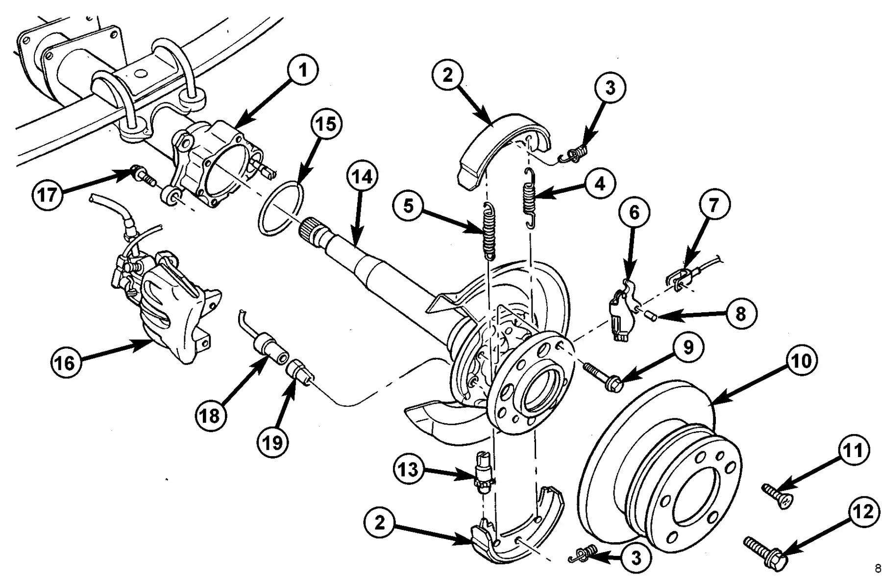
Fig. 6 AXLE SHAFT
- 1 - REAR AXLE
- 2 - BRAKE SHOE
- 3 - PRESSURE SPRING
- 4 - RETURN SPRING
- 5 - RETURN SPRING
- 6 - CABLE LOCK
- 7 - PARK BRAKE CABLE
- 8 - LOCKING PIN
- 9 - BOLT
- 10 - BRAKE DISC
- 11 - BOLT
- 12 - WHEEL BOLT
- 13 - BRAKE ADJUSTER
- 14 - REAR AXLE SHAFT
- 15 - GASKET
- 16 - BRAKE CABLE
- 17 - BOLT
- 18 - ABS SENSOR
- 19 - SENSOR BUSHING
- Remove wheels.
- Detach the front brake cable.
- Pull ABS sensor (18) together with clamp bushing (19) out of bearing cap (Fig. 6).
- Remove brake caliper (16) and disk (10) at rear axle (14). Attach brake caliper with lines connected in wheel house.
- Remove brake shoes (2) of parking brake.
- Remove brake control cable lock.
- Remove bearing cap bolts (17) and pull axle shaft out of axle tube (1) (Fig. 6).
- Remove seal/gasket.
SINGLE REAR WHEEL - AXLE INSTALLATION
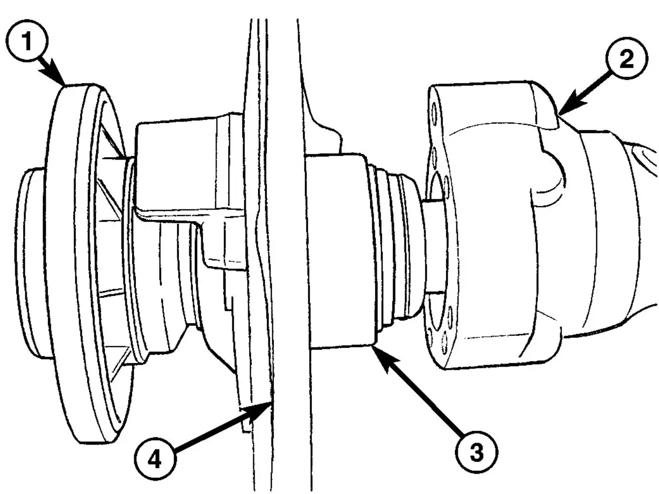
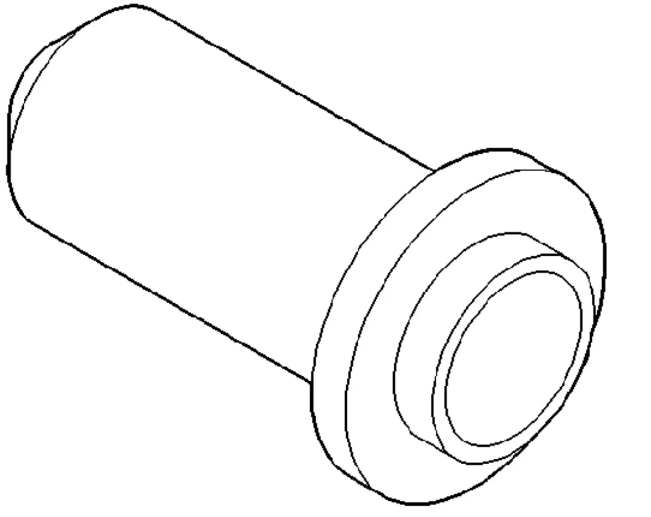
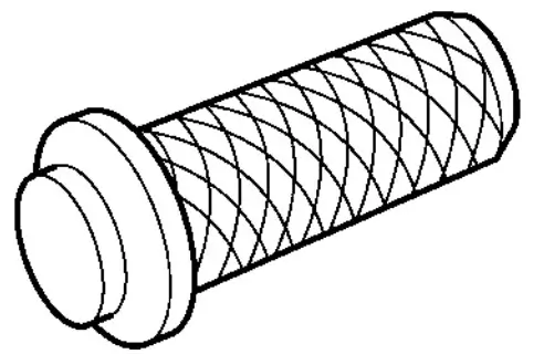
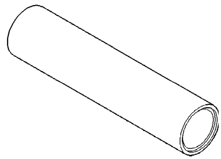
Fig. 7 AXLE SHAFT AND TUBE
- 1 - AXLE SHAFT
- 2 - AXLE TUBE
- 3 - AXLE BEARINGS
- 4 - DUST SHIELD
(1) Install sealing ring.
(2) Install axle shaft (1) in the axle tube (2) (Fig.7).
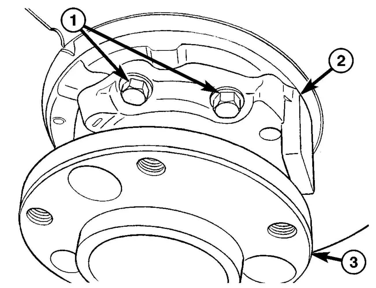
Fig. 8 BEARING CAP BOLTS
- 1 - BEARING CAP BOLTS
- 2 - BEARING CAP
- 3 - AXLE SHAFT FLANGE
(3) Install new bearing cap (2) bolts (1) and tighten to 72 N·m (53 ft. lbs.) (Fig. 8).
(4) Install brake control cable lock.
(5) Install parking brake shoes.
(6) Install brake disk and calipers.
(7) Coat clamping bush with acid-free grease. Insert ABS sensor with clamping bush fully into the mounting hole.
(8) Install front brake cable.
(9) Operate brake pedal several times until brake pads contact brake discs (brake pressure built up).
(10) Install wheels.
SINGLE REAR WHEEL - AXLE BEARING / SEAL REMOVAL
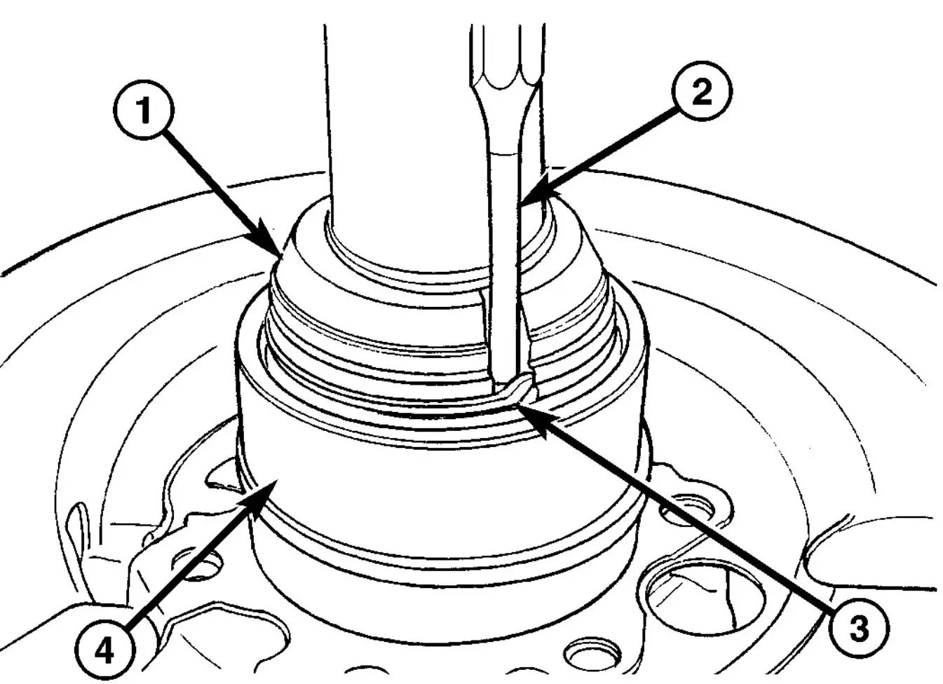
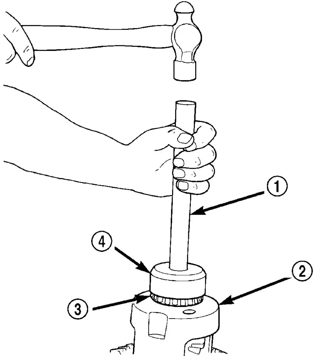
Fig. 9 LOCKING RING
- 1 - BEARING NUT
- 2 - PUNCH
- 3 - LOCKING RING
- 4 - BEARING
(1) Remove rear axle shaft.
(2) With a punch (2) and hammer straighten bearing (4) nut (1) locking ring (3) (Fig. 9).
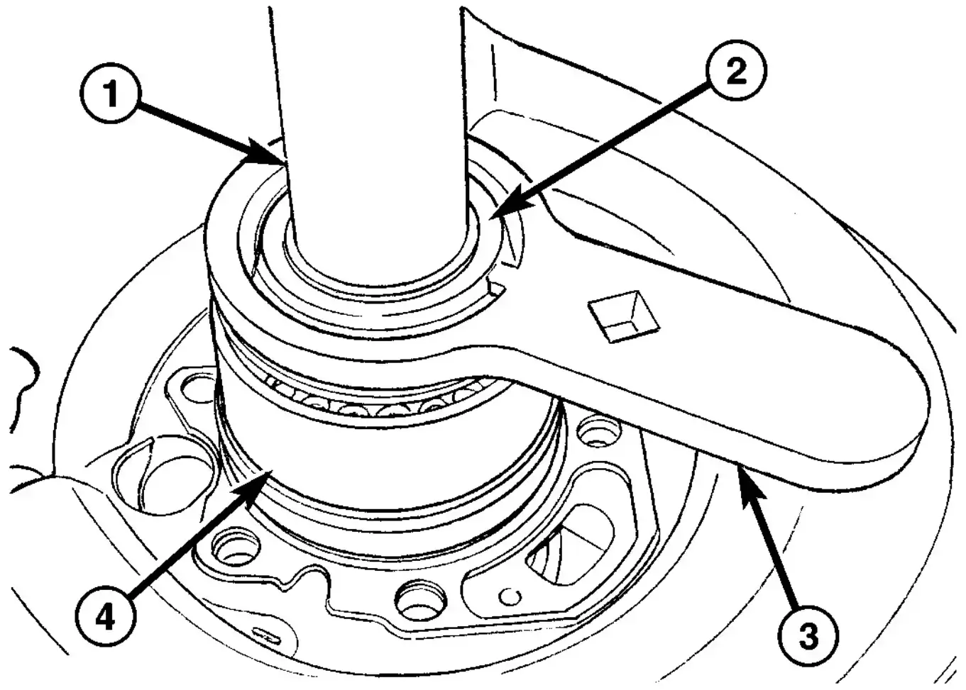
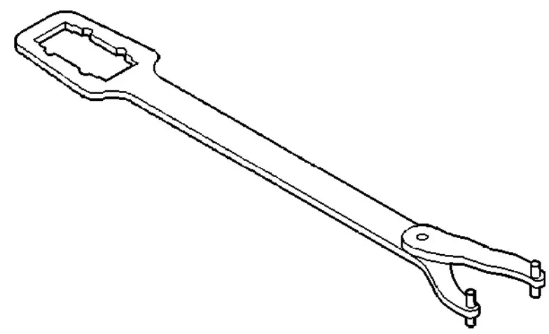
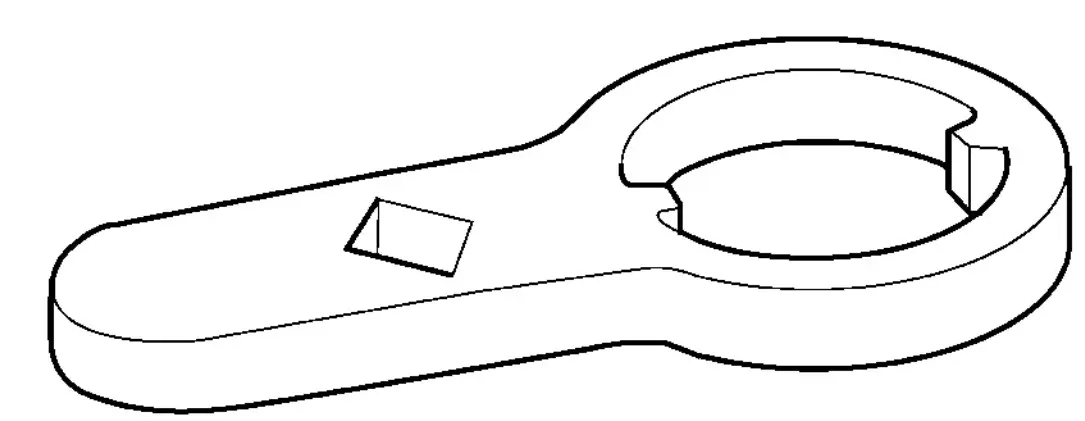
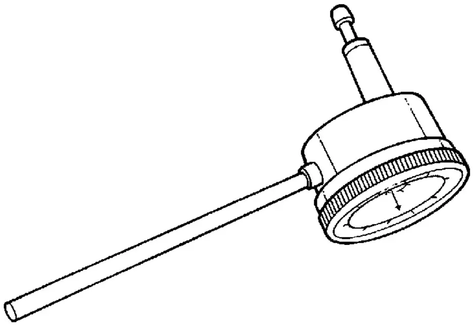
Fig. 10 BEARING NUT WRENCH
- 1 - AXLE SHAFT
- 2 - BEARING NUT
- 3 - WRENCH
- 4 - BEARING
(3) Install two wheel mounting bolts into the axle shaft (1) and clamp in vise. Loosen bearing (4) nut (2) with Wrench 9279 (3) (Fig. 10).
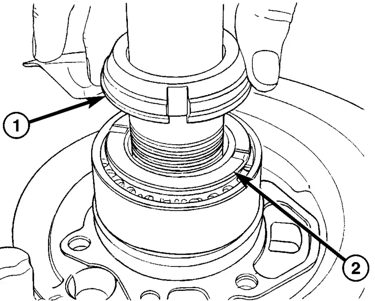
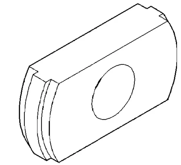
Fig. 11 BEARING NUT AND LOCKING RING
- 1 - BEARING NUT
- 2 - LOCKING RING
(4) Remove bearing nut (1) and locking ring (2) from an axle shaft (Fig. 11).
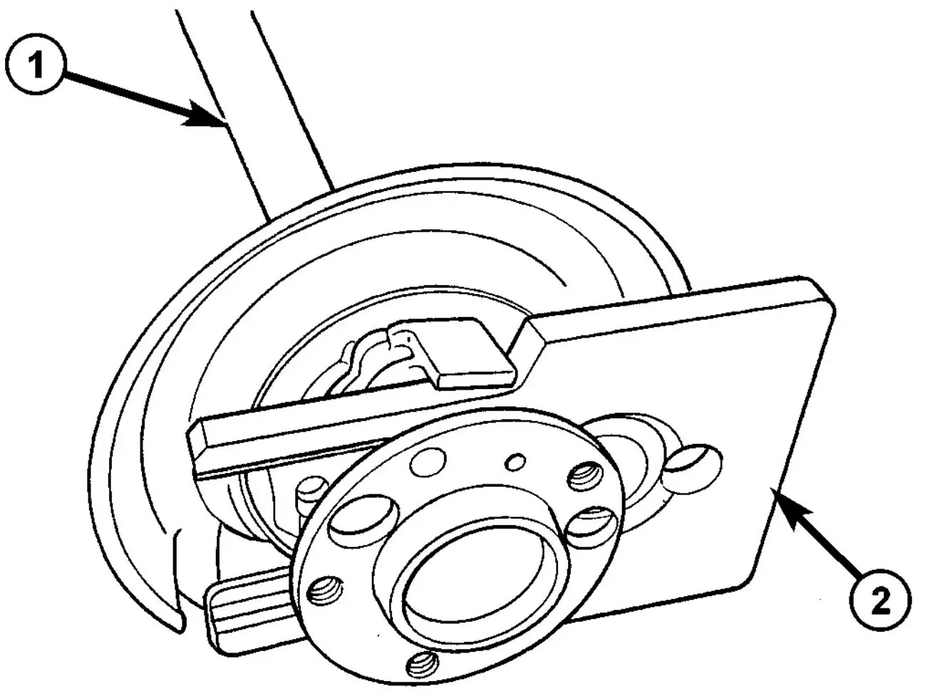
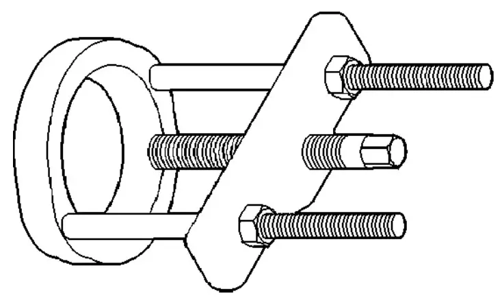
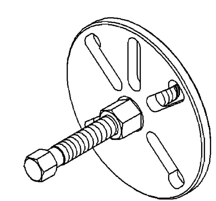
Fig. 12 AXLE BEARING REMOVAL TOOL
- 1 - AXLE SHAFT
- 2 - PLATE
(5) Push Plate 9277 (2) between bearing cover and axle shaft (1) (Fig. 12).
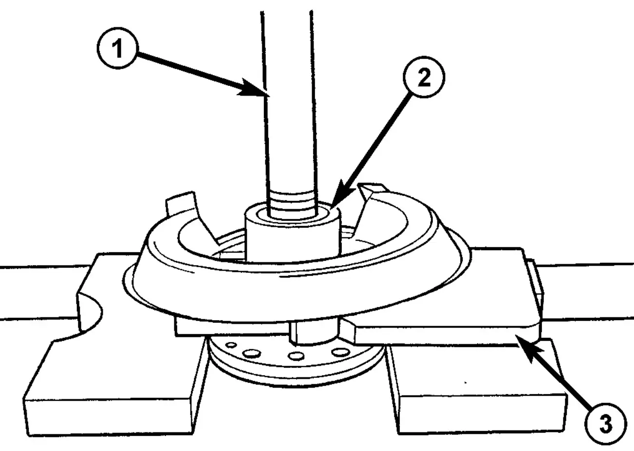
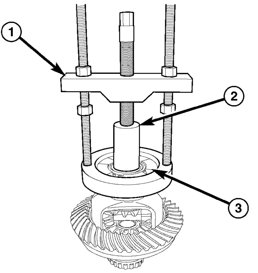
Fig. 13 PRESSING BEARING
- 1 - AXLE SHAFT
- 2 - BEARING
- 3 - PLATE
(6) Place axle shaft (1) with plate (3) in a press.
(7) Press axle shaft (1) through the bearing cover and tapered roller bearings (2) (Fig. 13).
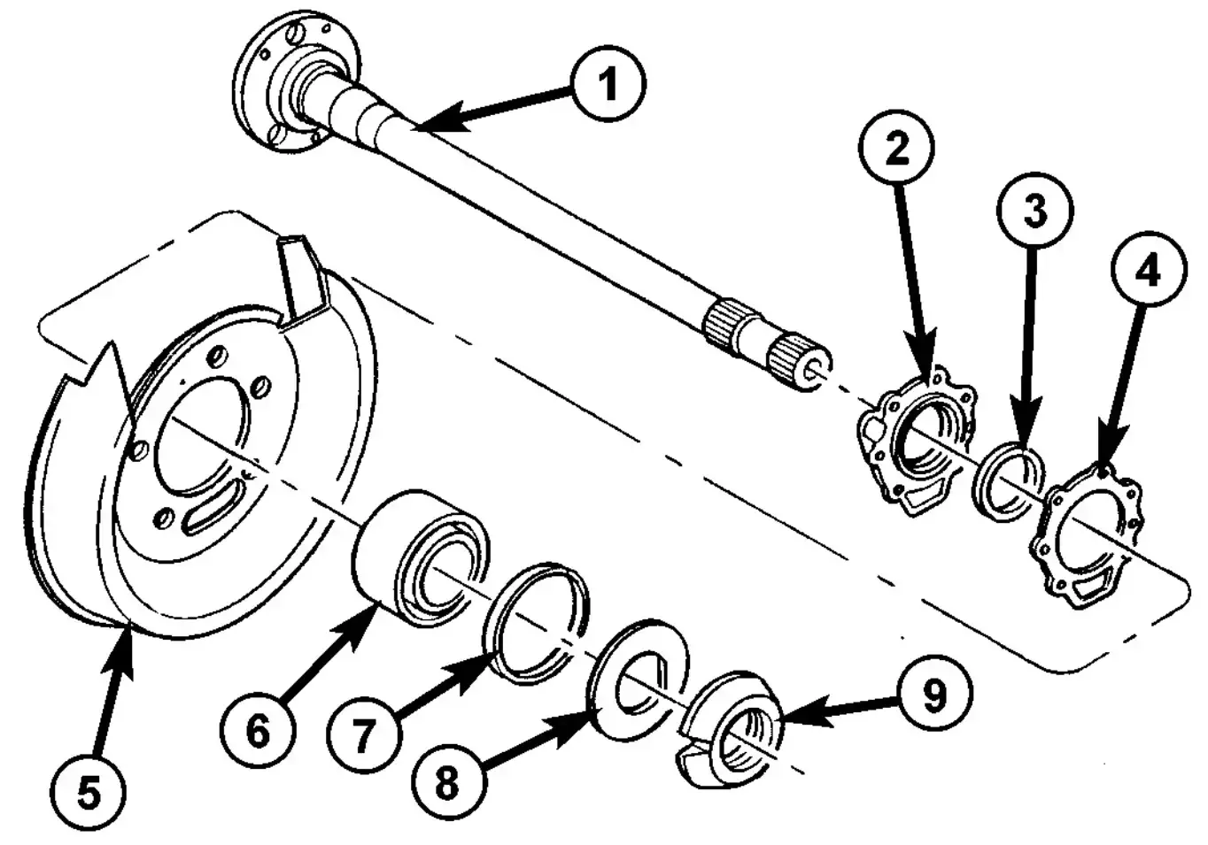
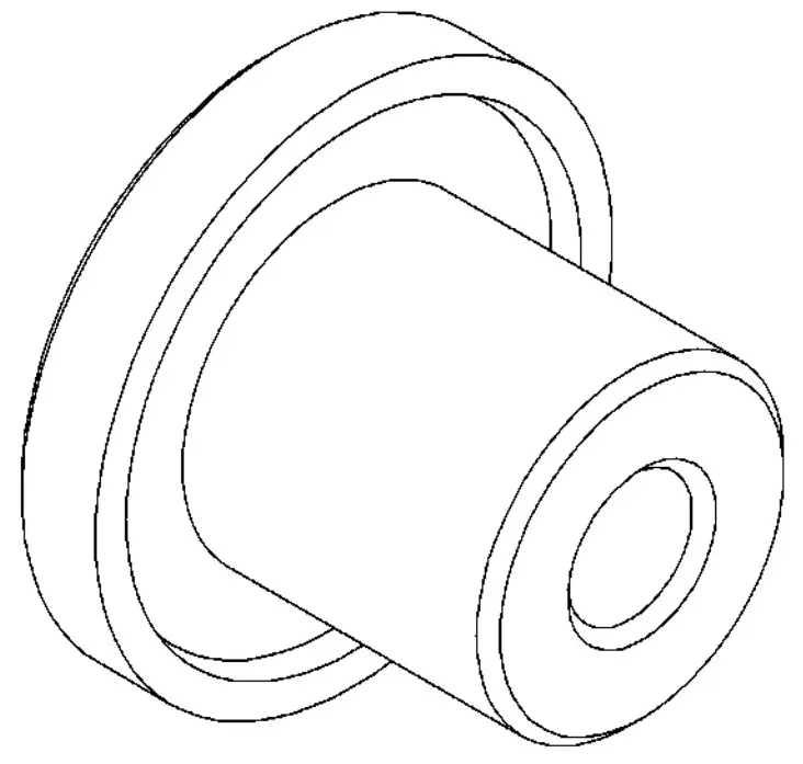
Fig. 14 AXLE SHAFT ASSEMBLY
- 1 - AXLE SHAFT
- 2 - BEARING COVER
- 3 - RADIAL SHAFT SEAL
- 4 - GASKET
- 5 - DUST SHIELD
- 6 - BEARING
- 7 - SEALING RING
- 8 - LOCKING RING
- 9 - BEARING NUT
(8) Remove tapered roller bearings (6), sealing ring (7), dust shield (5) and bearing cover (2) from axle shaft (1) (Fig. 14).
(9) Remove shaft seal (3) from bearing cover (2) with a hammer and drift.
SINGLE REAR WHEEL - AXLE BEARING / SEAL INSTALLATION
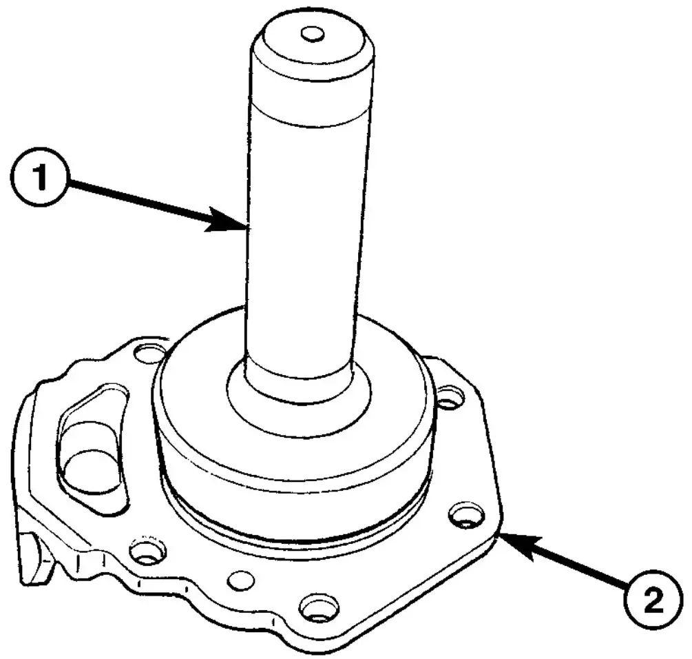
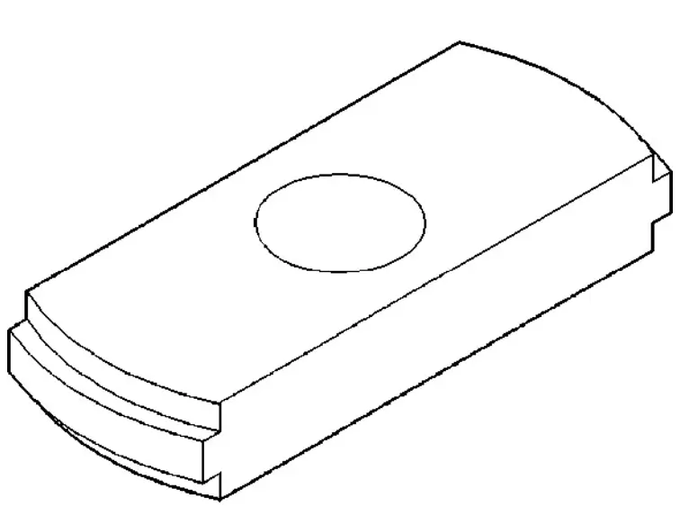
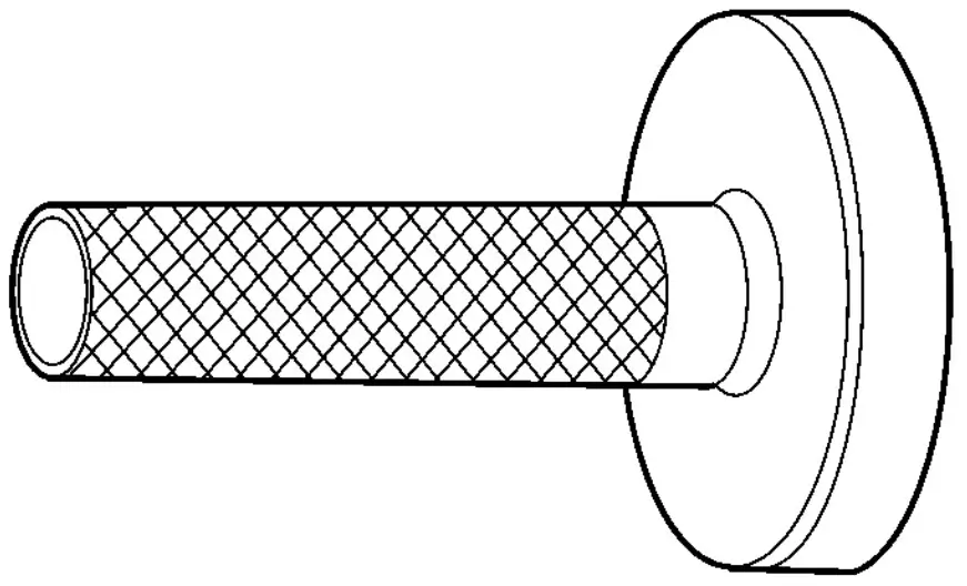
Fig. 15 SEAL INSTALLER
- 1 - INSTALLER
- 2 - BEARING COVER
(1) Clean sealing surface of bearing cap.
(2) Install axle shaft seal into bearing cover (1) with Installer 9278 (2) (Fig. 15).
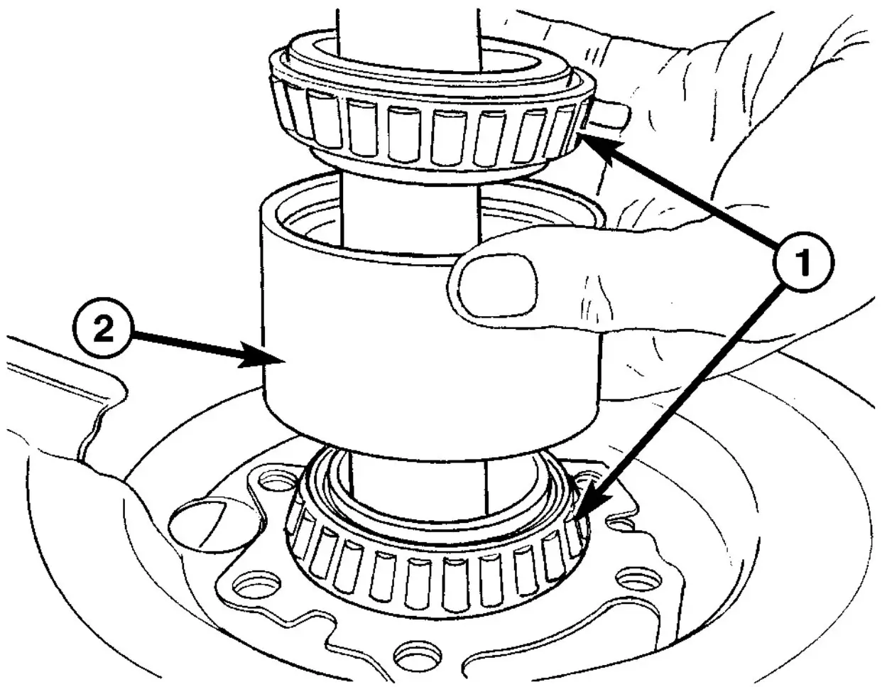
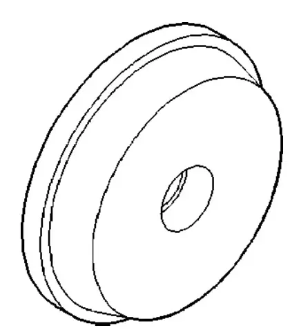
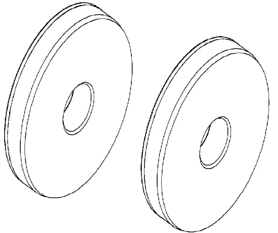
Fig. 16 BEARINGS AND RACE
- 1 - BEARINGS
- 2 - RACE
(3) Check roller bearing (1), and replace if necessary.
(4) Install bearing cover with axle shaft seal, new gasket and dust shield on the axle shaft.
(5) Install tapered roller bearings (1) and race (2) on the axle shaft (Fig. 16).
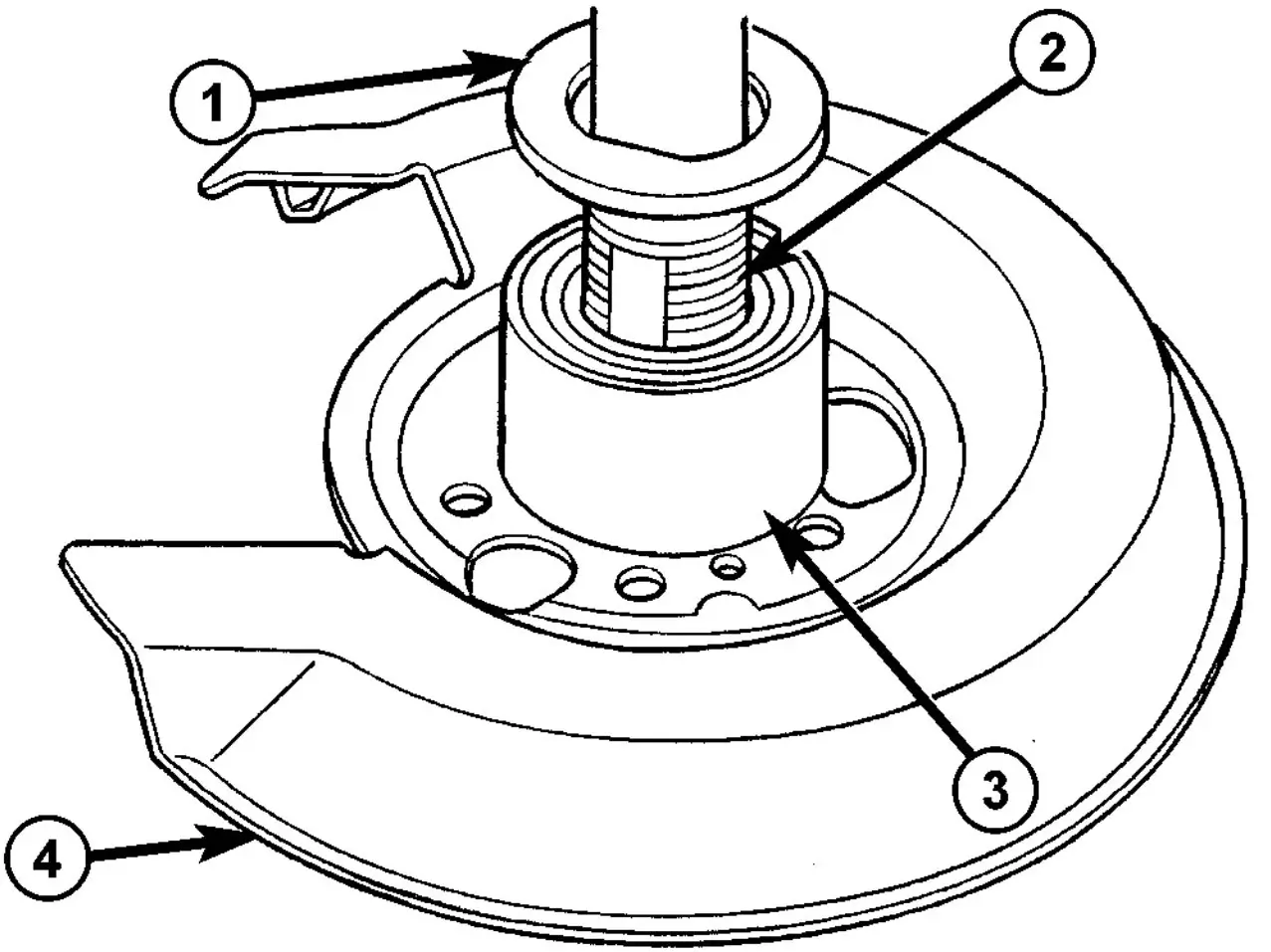
Fig. 17 BEARING AND SHAFT
- 1 - LOCKING RING
- 2 - AXLE SHAFT
- 3 - BEARING
- 4 - DUST SHIELD
(6) Install new locking ring (1) on axle shaft (2).
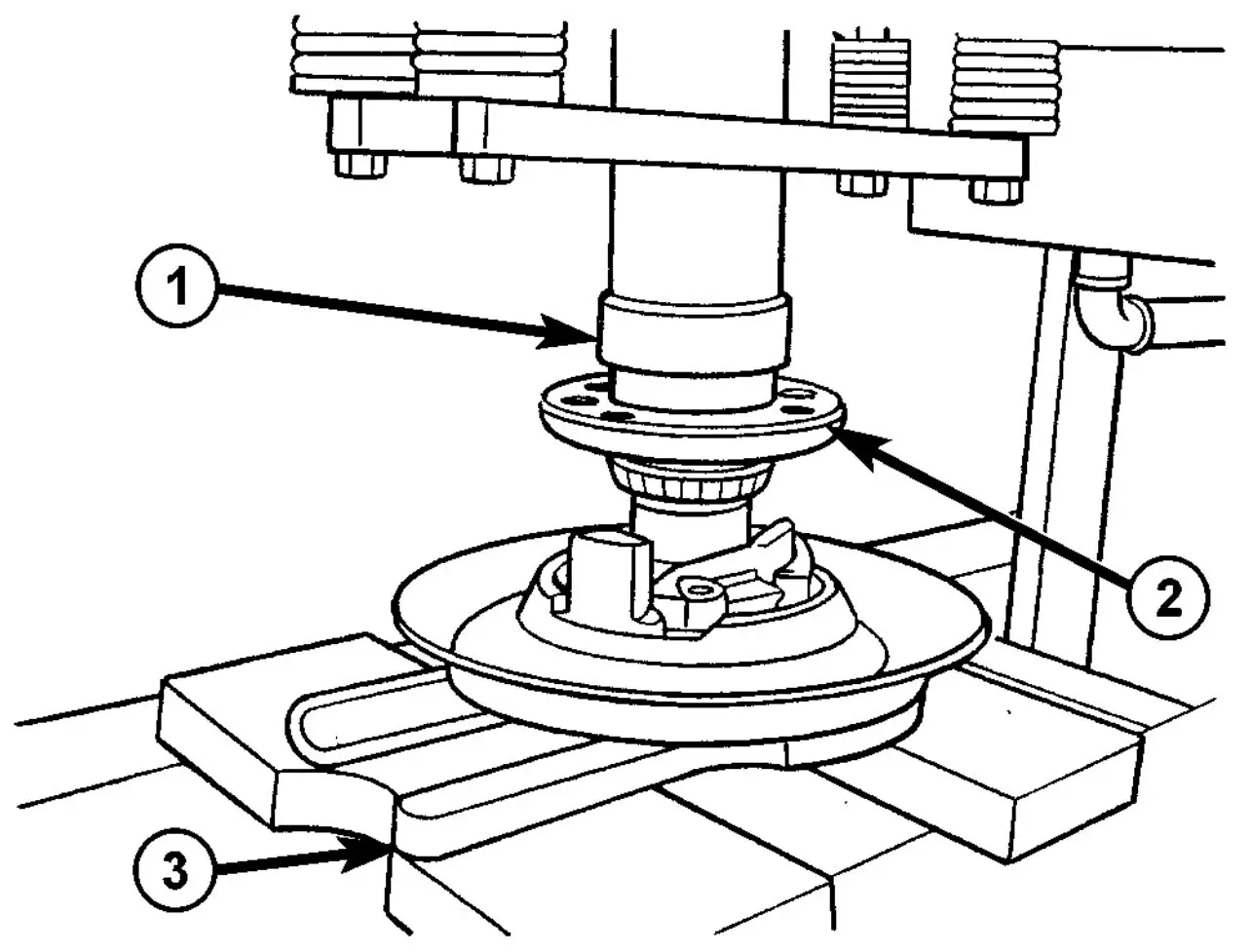
Fig. 18 PRESSING AXLE SHAFT
- 1 - PRESS
- 2 - AXLE SHAFT
- 3 - PLATE
(7) Place the axle shaft (2) through the hole in Plate 9277 (3) and position the assembly in a press (1) (Fig. 18).
(8) Press tapered roller bearing onto a rear axle shaft as far as the stop.
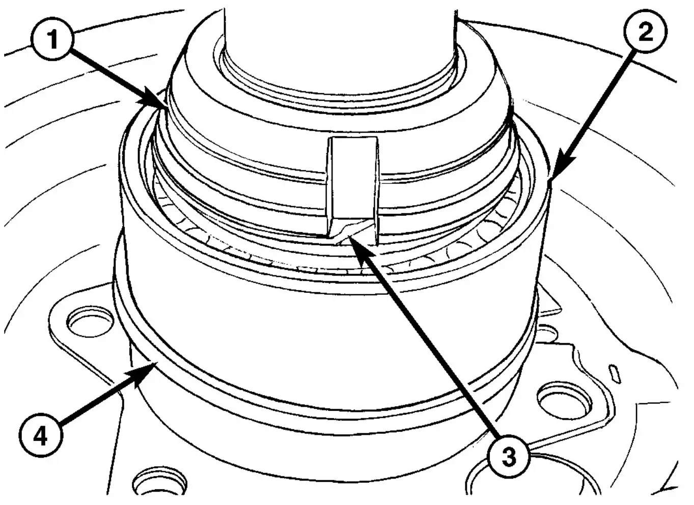
Fig. 19 LOCKING RING
- 1 - BEARING NUT
- 2 - BEARING
- 3 - LOCKING RING
- 4 - SEALING RING
(9) Screw on bearing nut (1) and tighten nut with Wrench 9279 to 500 N·m (369 ft. lbs.).
(10) Bend locking ring (3) with a hammer and punch at both grooves in the bearing nut (Fig. 19).
(11) Install sealing ring (4) onto roller bearing race (Fig. 19).
(12) Install rear axle shaft.
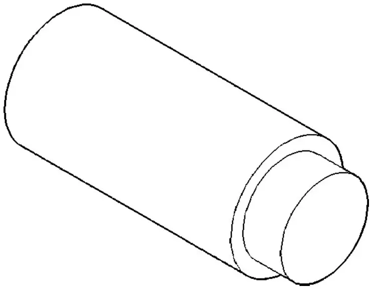
DUAL REAR WHEELS - SHAFT REMOVAL
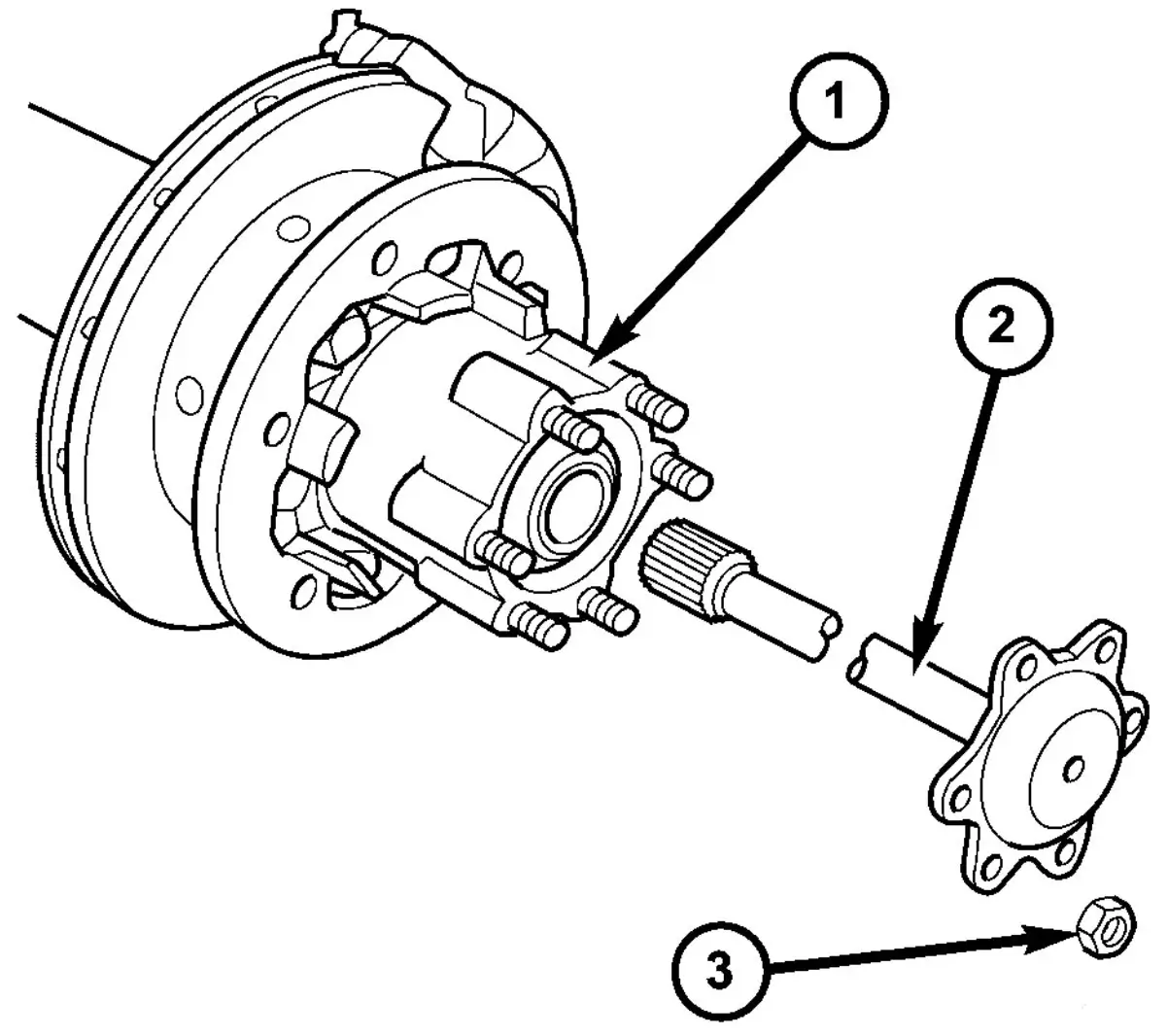
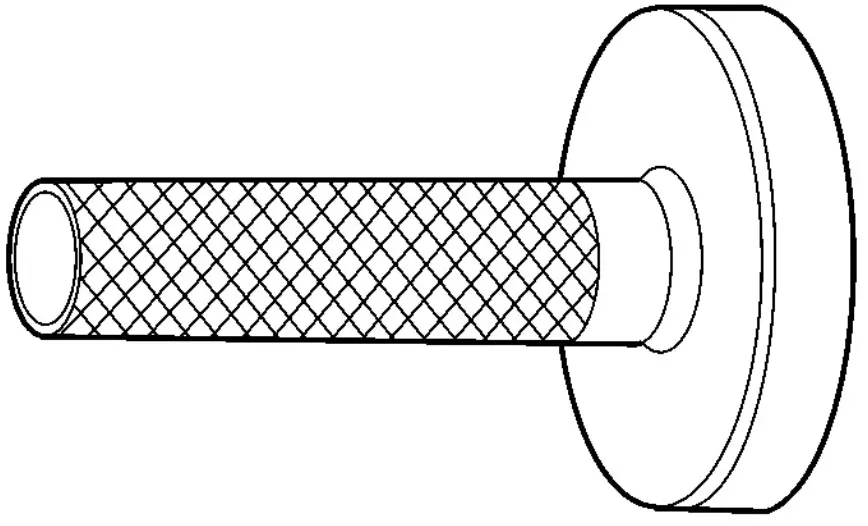
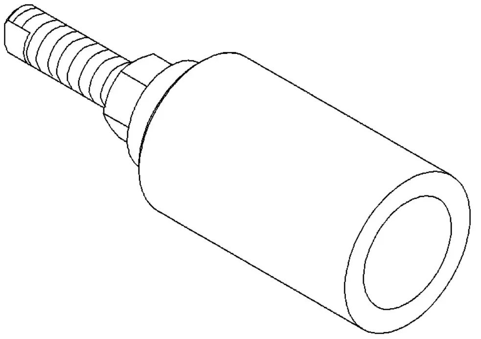
Fig. 20 AXLE SHAFT
- 1 - WHEEL HUB
- 2 - AXLE SHAFT
- 3 - AXLE NUT
(1) Remove wheelst.
(2) Remove axle shaft (2) hub (1) nuts (3) (Fig. 20).
(3) Pull out axle shaft.
DUAL REAR WHEELS - SHAFT Installation
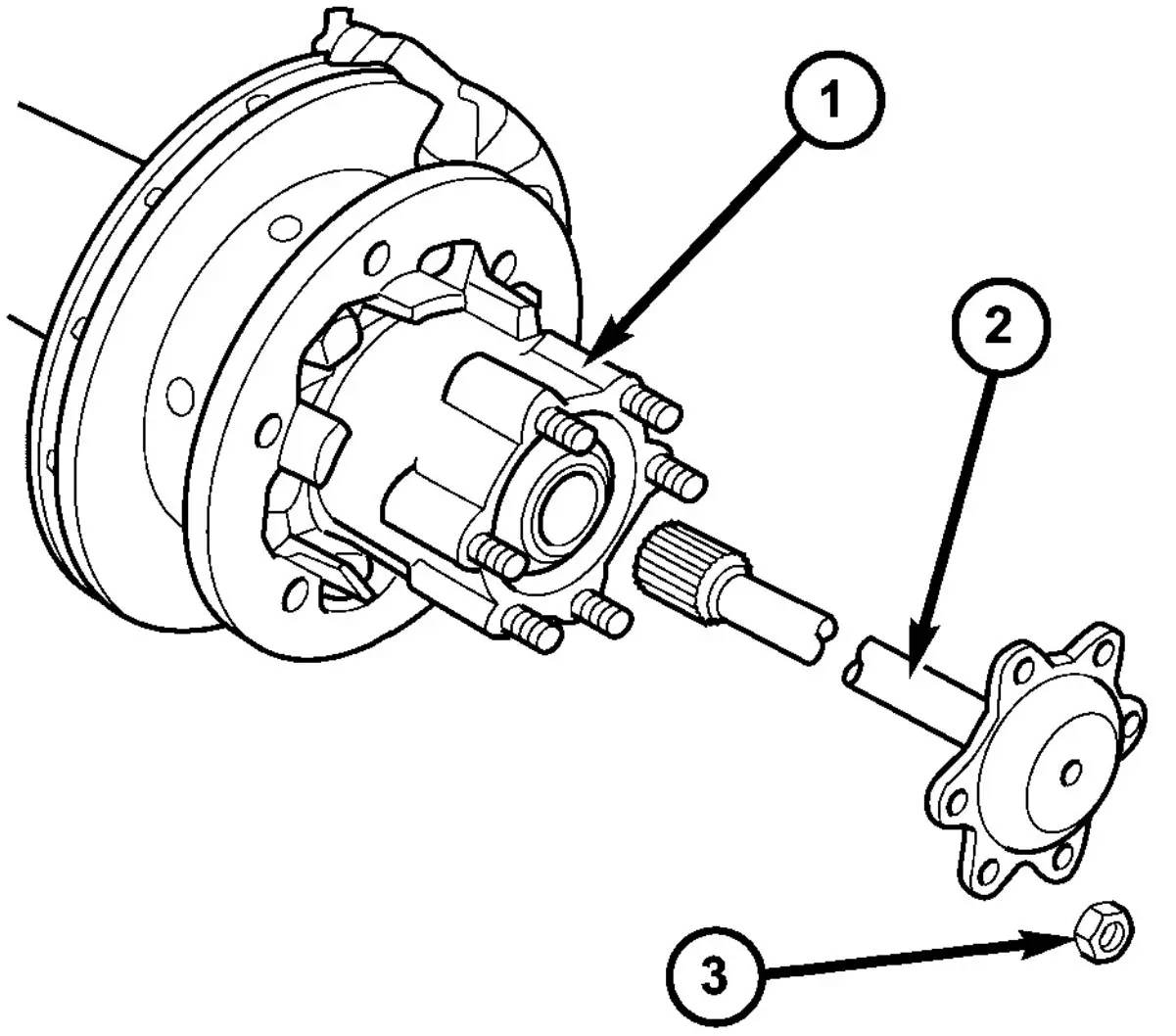
Fig. 21 AXLE SHAFT
- 1 - WHEEL HUB
- 2 - AXLE SHAFT
- 3 - AXLE NUT
(1) Coat axle shaft flange with Mopar Metal Assembly Paste.
(2) Slide axle shaft (2) into axle tube.
(3) Install axle shaft hub (1) nuts (3) and tighten to N·m 65 (48 ft. lbs.) (Fig. 21).
(4) Install wheels.
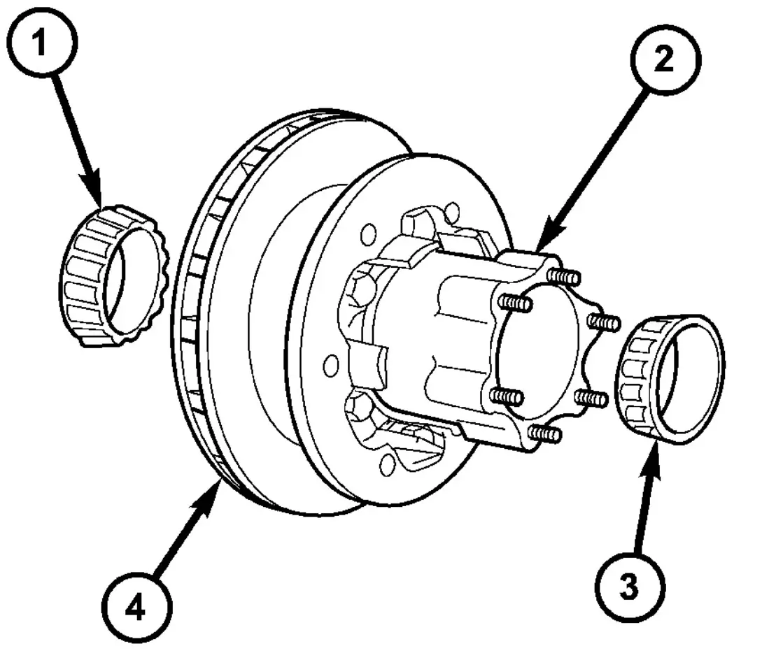
DUAL REAR WHEEL - AXLE BEARING / SEAL REMOVAL
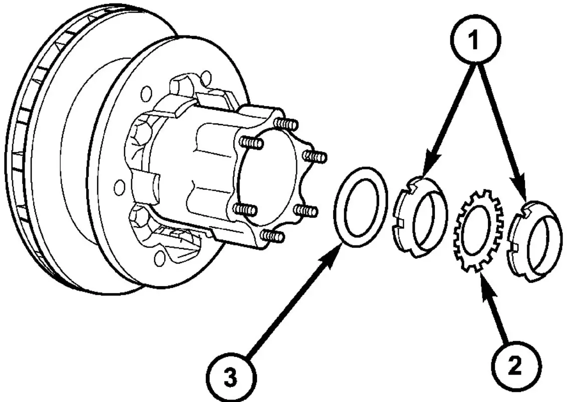
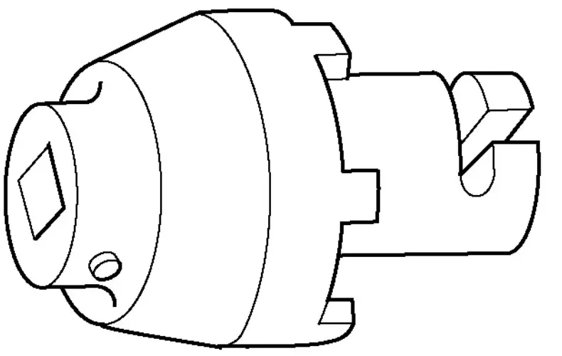
Fig. 22 HUB NUTS
- 1 - NUTS
- 2 - OCKING PLATE
- 3 - THRUST WASHER
(1) Remove brake caliper with support.
(2) Remove axle shaft.
(3) Back-off parking brakes.
(4) Remove outer hub nut (1) with Wrench 9290 (Fig. 22).
(5) Remove locking plate (2), inner hub nut (1) and thrust washer (3) (Fig. 22).
(6) Pull hub off axle tube.
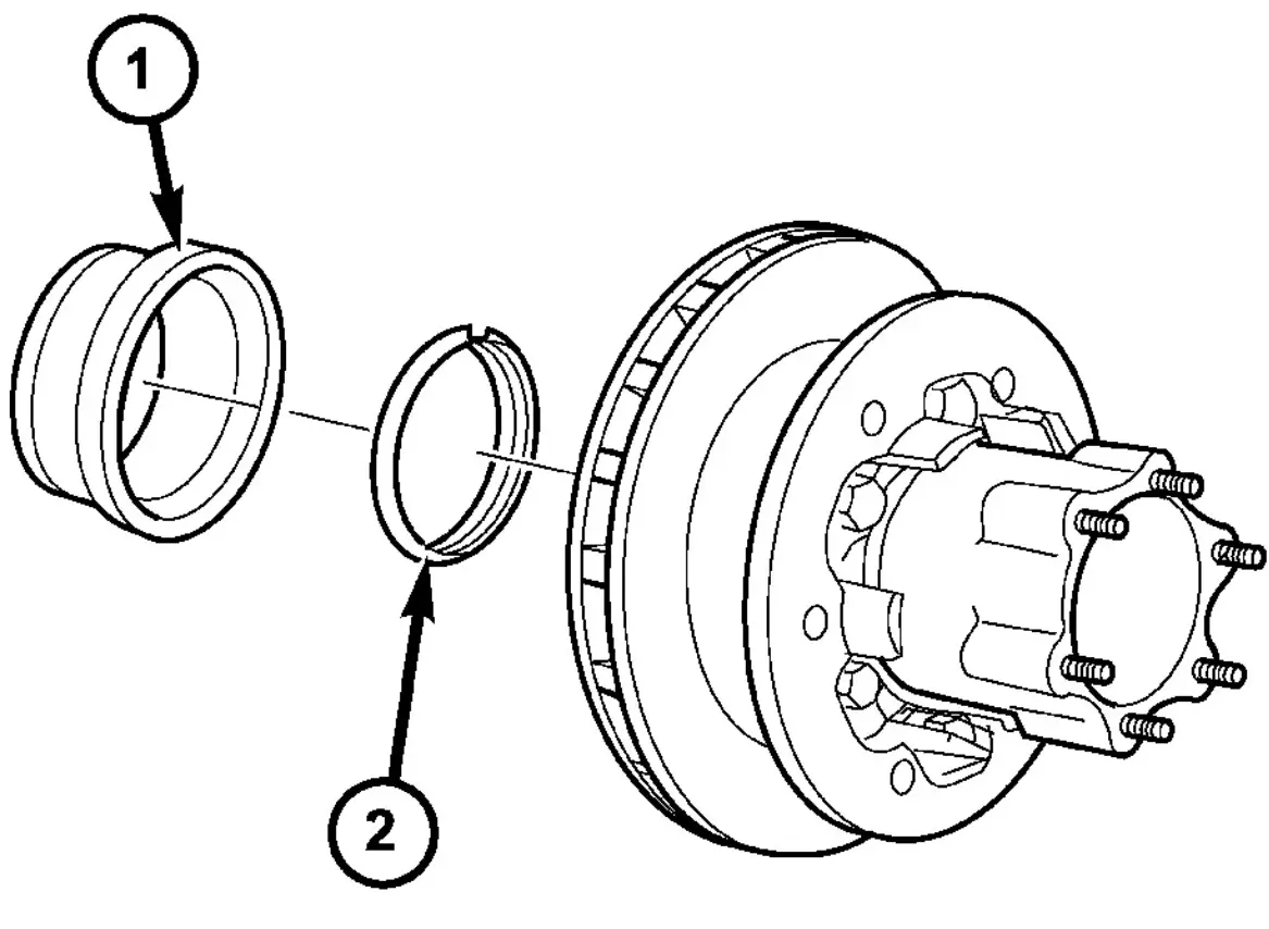
Fig. 23 SENSOR RING & OIL SEA
- 1 - ABS SENSOR RING
- 2 - SEAL
DUAL REAR WHEEL - AXLE BEARING / SEAL INSTALLATION
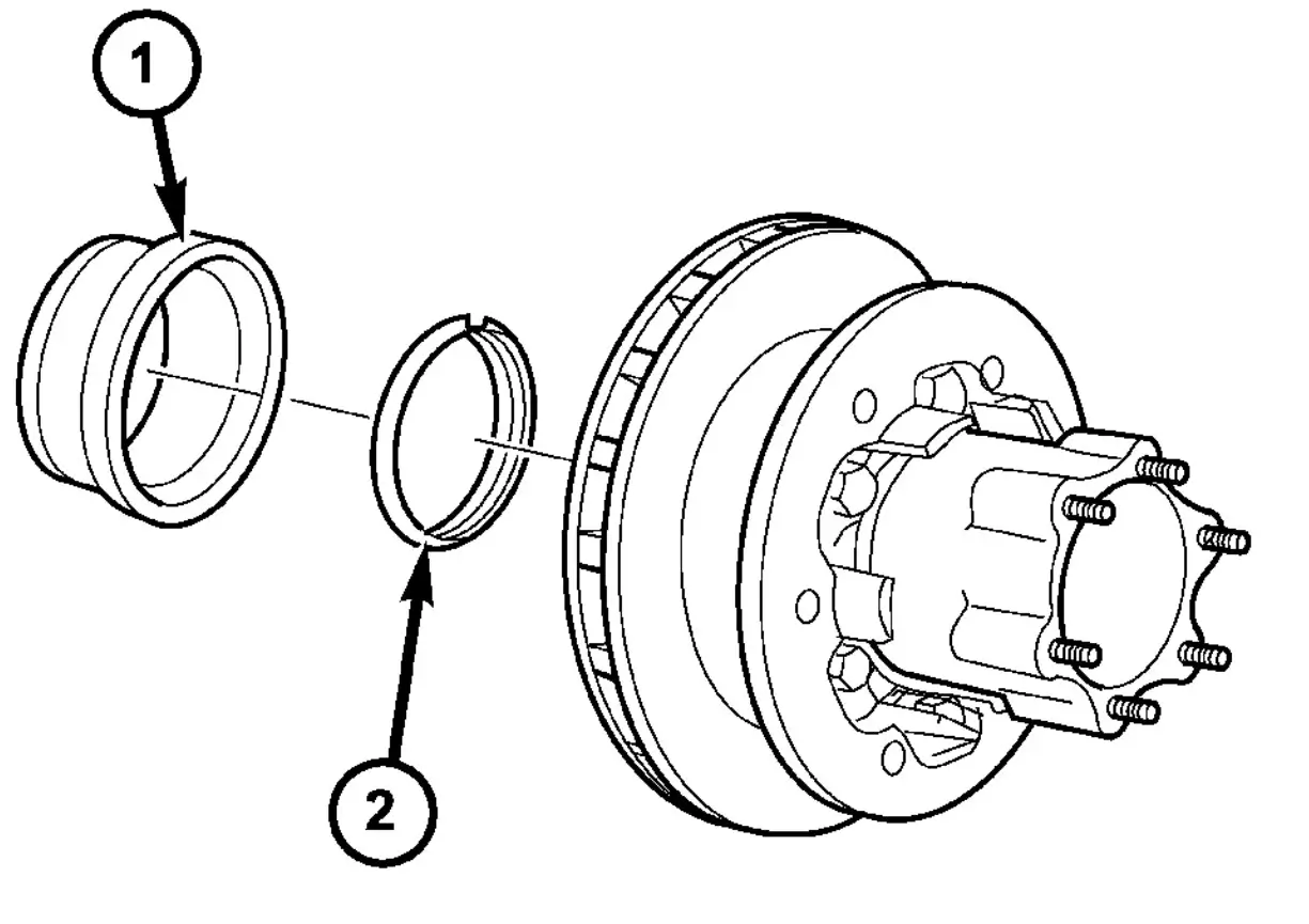
Fig. 25 SENSOR RING & OIL SEAL
- 1 - ABS SENSOR RING
- 2 - SEAL
(1) Install hub bearing cups with Installer 9291 and a hammer.
(2) Clean and thoroughly grease bearings with Multi-purpose grease.
(3) Install inner-wheel bearing.
(4) Coat the outer circumference of new seal (2) with Hylomar SQ 32 M sealant.
(5) Install seal (2) into hub with an appropriate installer.
(6) Coat contact surface of ABS sensor ring (1) with Hylomar SQ 32 M sealant (Fig. 25).
(7) Drive ABS sensor ring (1) in as far as the stop with a plastic hammer (Fig. 25).
(8) Install hub on axle tube.
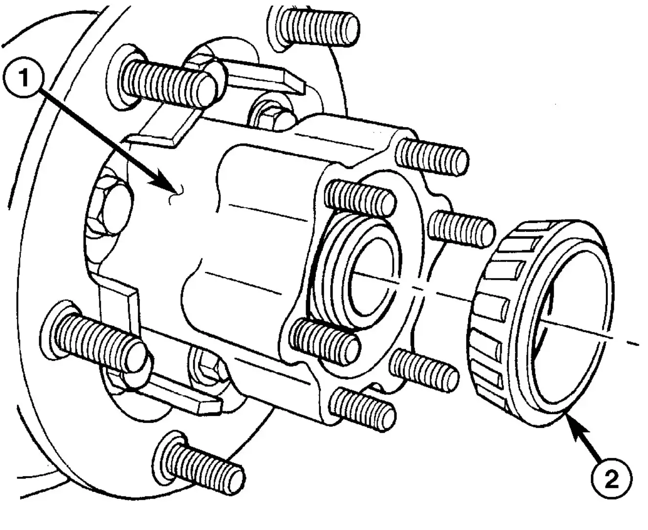
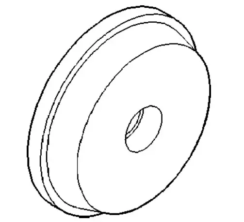
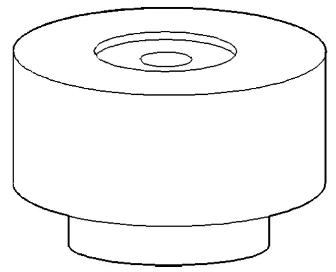
Fig. 26 OUTER HUB BEARING
- 1 - HUB
- 2 - BEARING
(9) Install outer hub (1) bearing (2) (Fig. 26).

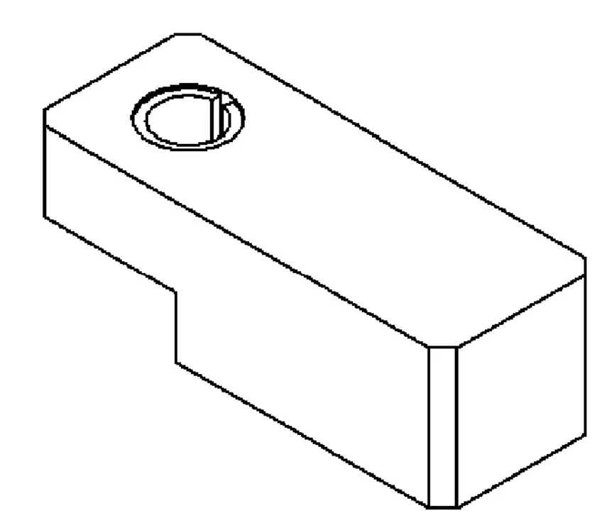
Fig. 27 THRUST WASHER
- 1 - HUB
- 2 - WASHER
(10) Install thrust washer (2) (Fig. 27).
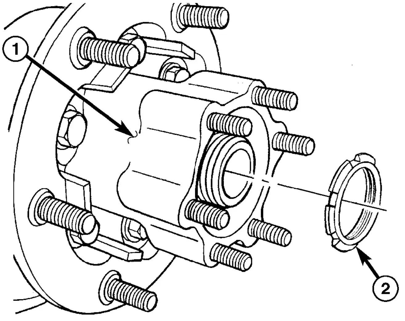
Fig. 28 INNER HUB NUT
- 1 - HUB
- 2 - NUT
(11) Install inner hub (1) nut (2) (Fig. 28).
(12) Tighten inner hub nut with Wrench 9290 to 300 N·m (221 ft. lbs.) while spinning the wheel hub constantly. Turn back inner nut and then tighten until it touches the thrust washer without play. Then tighten 1/8 turn.).
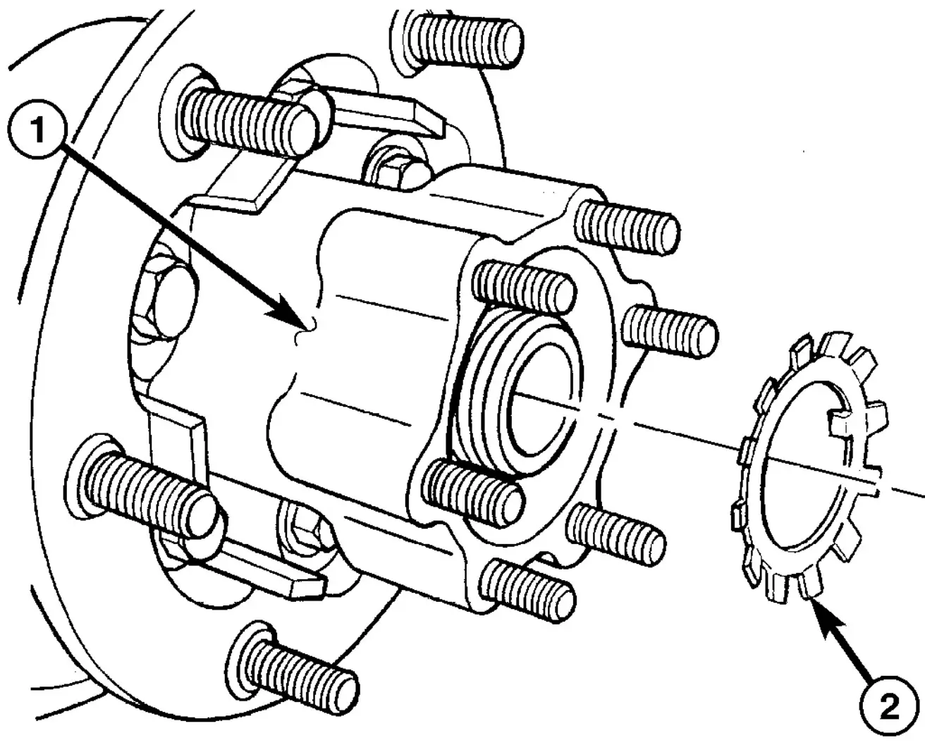
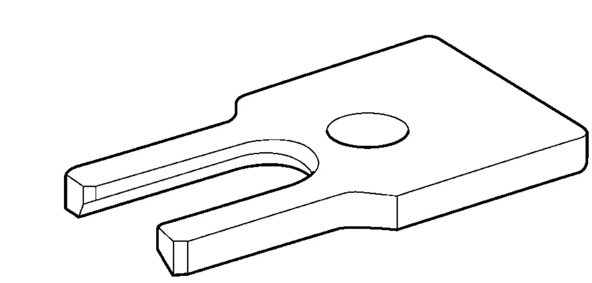
Fig. 29 LOCKING PLATE
- 1 - HUB
- 2 - PLATE
(13) Install locking plate (2) (Fig. 29).
(14) Install outer hub nut and tighten with Wrench 9290 to 250 N·m (184 ft. lbs.).
(15) Install axle shaft.
(16) Install brake caliper and support.
(17) Adjust parking brakes.
DIFFERENTIAL - REMOVAL
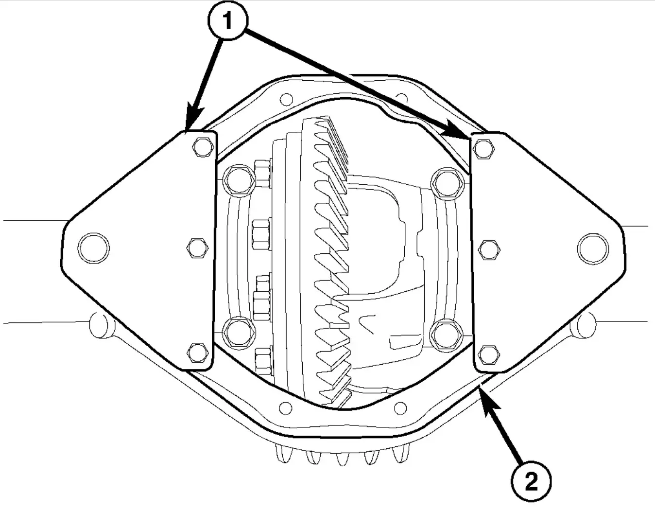
Fig. 30 SPREADER ADAPTERS
- 1 - ADAPTERS
- 2 - DIFFERENTIAL HOUSING
(1) Remove differential fill plug.
(2) Remove differential cover and drain fluid.
(3) Remove axle shafts.
(4) Mark bearing caps and housing for installation reference.
(5) Remove differential bearing cap bolts.
(6) Mount Adapters 9317 (1) (Fig. 30) on differential housing (2)
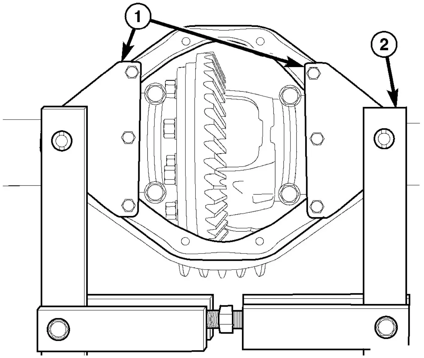
Fig. 31 SPREADER
- 1 - ADAPTERS
- 2 - SPREADER
(7) Position Spreader W-129-B (2) on adapters (1) (Fig. 31). Mount dial indicator on housing to measure housing spread.
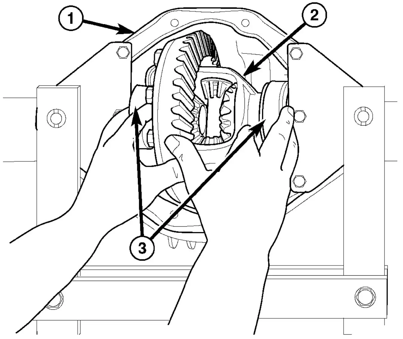
Fig. 32 DIFFERENTIAL REMOVAL
- 1 - HOUSING
- 2 - DIFFERENTIAL
- 3 - DIFFERENTIAL BEARINGS
(8) Remove differential (2) with bearings, cups (3) and differential shims (Fig. 32).
(9) Mark bearings and shims for installation reference.
(10) Clean the housing cavity with flushing oil, light engine oil or lint-free cloth.
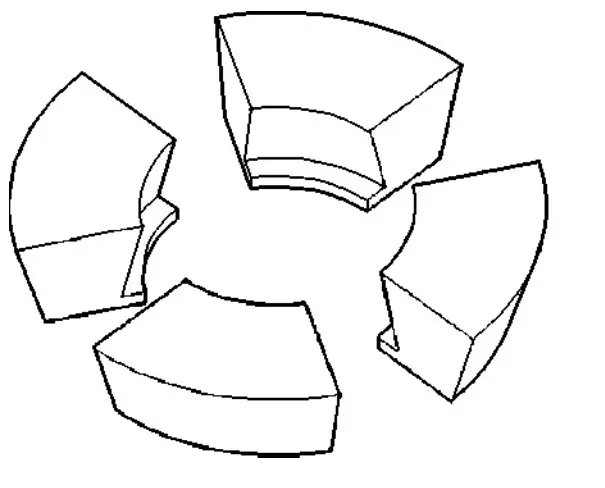
SINGLE REAR WHEEL DIFFERENTIAL - DISASSEMBLY
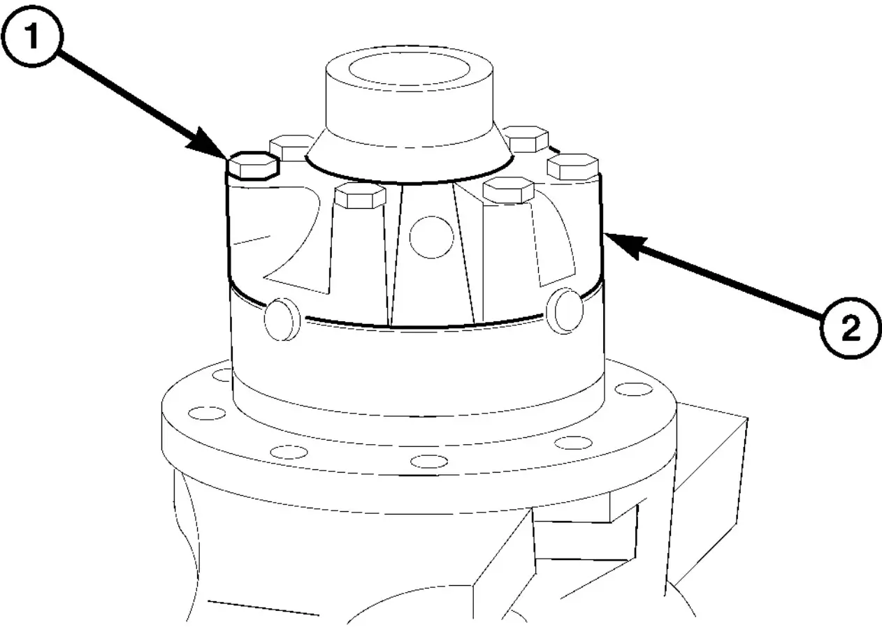
Fig. 33 DIFFERENTIAL COVER
- 1 - BOLTS
- 2 - COVER
(1) Remove differential cover bolts and remove cover (Fig. 33).
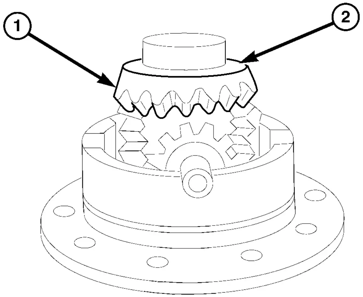
Fig. 34 UPPER SIDE GEAR
- 1 - SIDE GEAR
- 2 - SHIM
(2) Remove upper differential side gear (1) and shim (2) (Fig. 34).
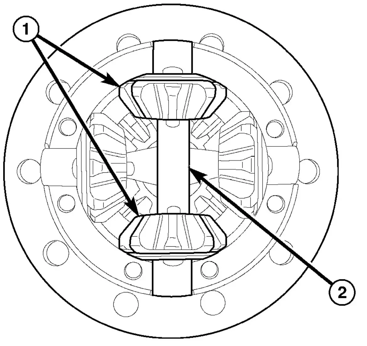
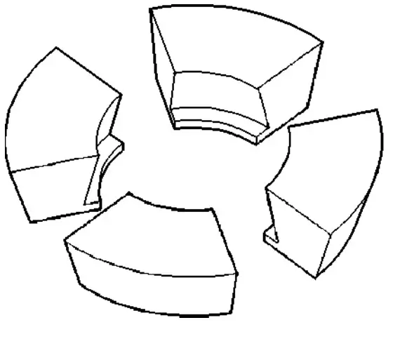
Fig. 35 FIRST PINION GEARS
- 1 - PINION GEARS
- 2 - MATE SHAFT
(3) Remove the first set of differential pinion gears (1), spherical washers and mate shaft (2) (Fig. 35).
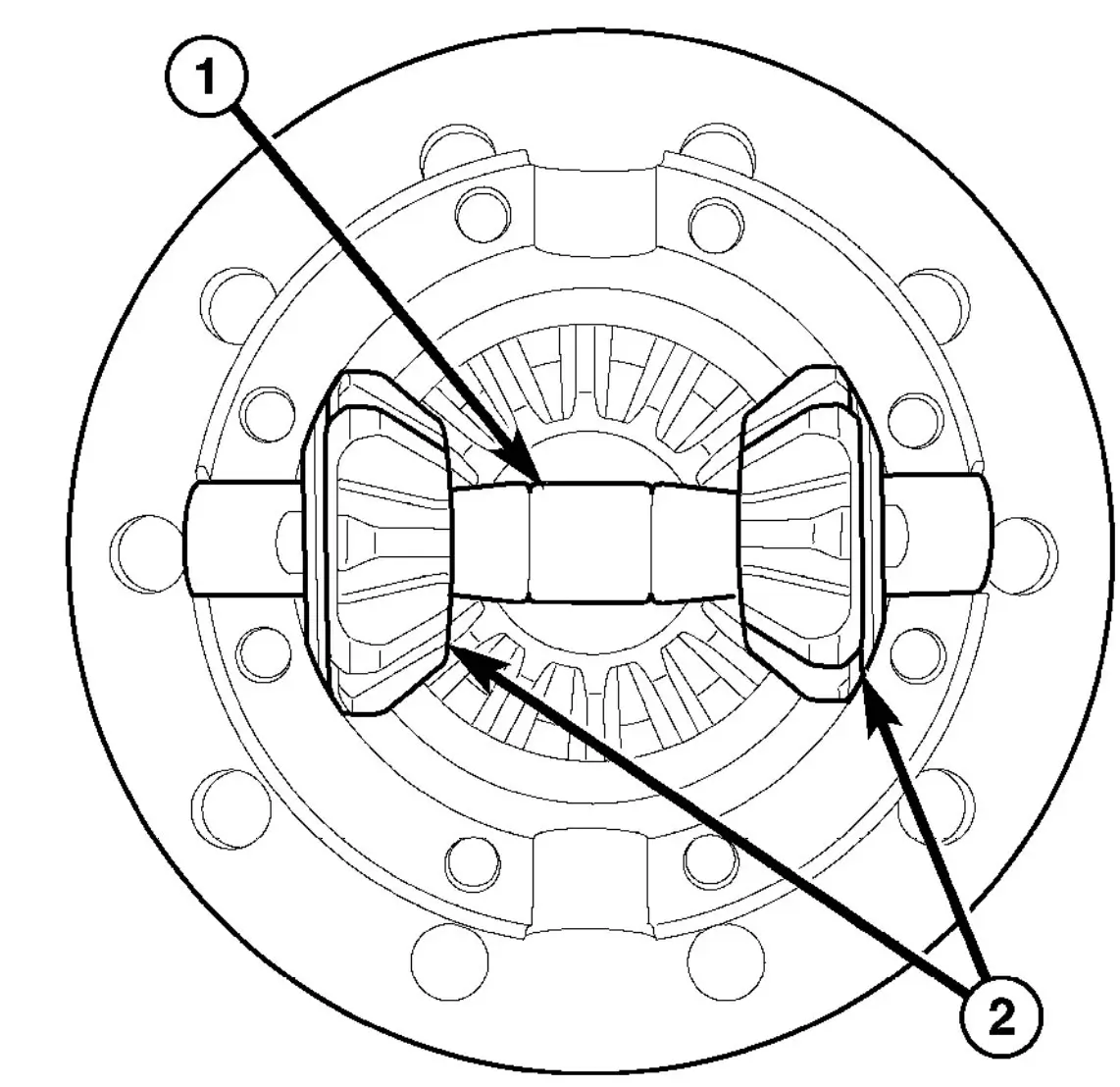
Fig. 36 SECOND PINION GEAR SET
- 1 - MATE SHAFT
- 2 - PINION GEARS
(4) Remove the second set of differential pinion gears (2), spherical washers and mate shaft (1) (Fig. 36).
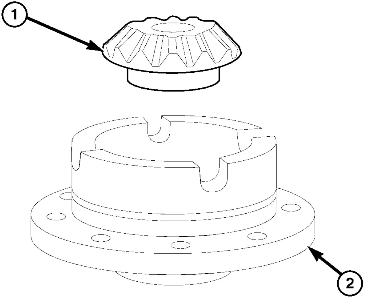
Fig. 37 LOWER SIDE GEAR
- 1 - SIDE GEAR
- 2 - DIFFERENTIAL CASE
(5) Remove lower differential side gear (1) and shim (Fig. 37).
DUAL REAR WHEELS DIFFERENTIAL - DISASSEMBLY

Fig. 38 DIFFERENTIAL COVER
- 1 - BOLTS
- 2 - COVER
(1) Remove differential cover bolts and remove cover (Fig. 38).
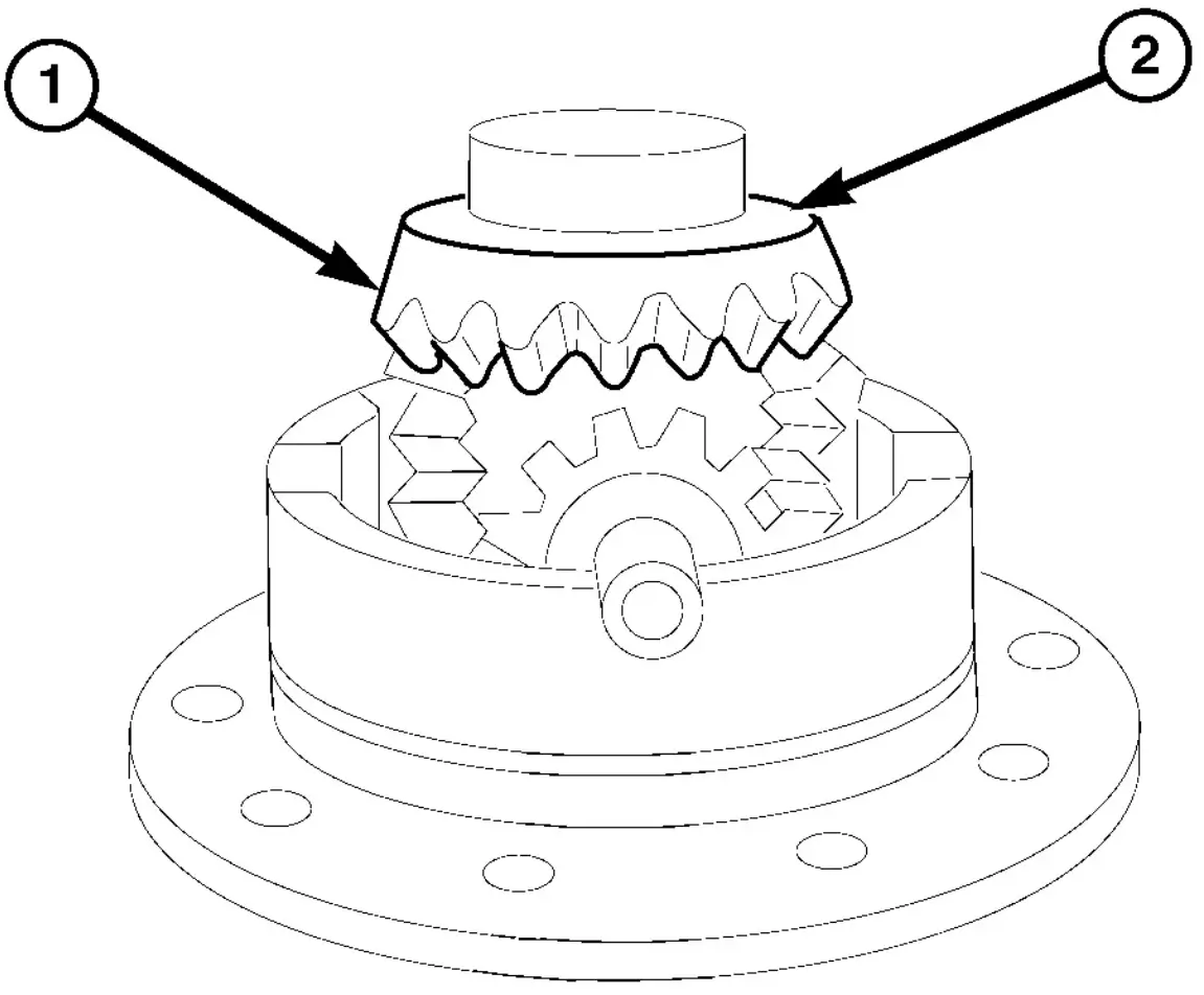
Fig. 39 UPPER SIDE GEAR
- 1 - SIDE GEAR
- 2 - SHIM
(2) Remove upper differential side gear (1) and shim (2) (Fig. 39).
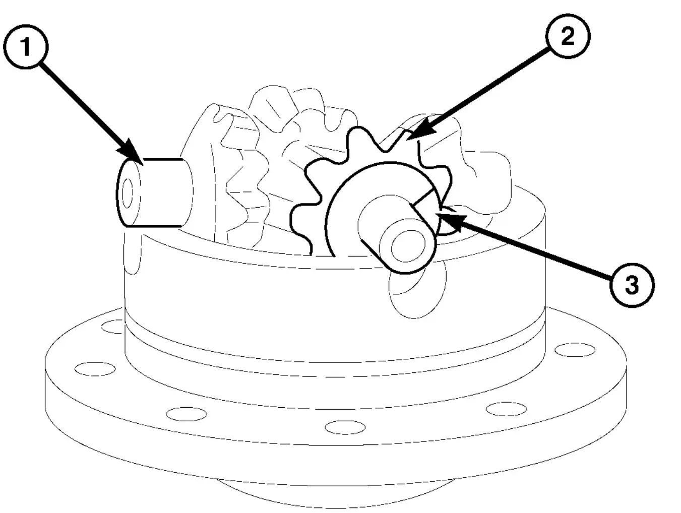
Fig. 40 DIFFERENTIAL PINIONS
- 1 - CROSS SHAFT
- 2 - PINION GEAR
- 3 - WASHER
(3) Remove differential cross shaft (1) with pinion gears (2) and spherical washers (3) (Fig. 40).
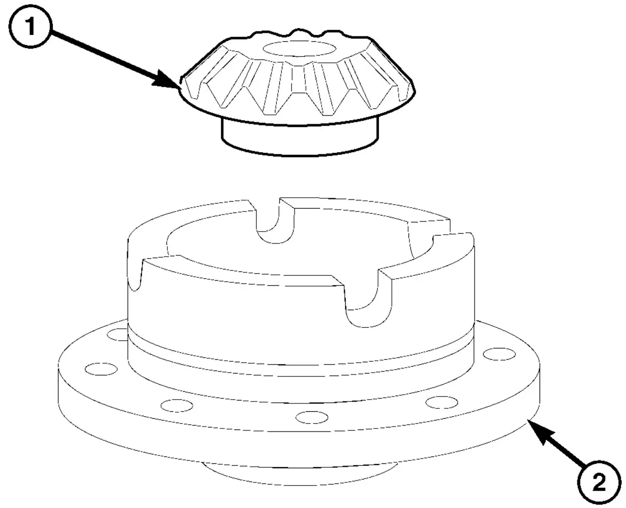
Fig. 41 LOWER SIDE GEAR
- 1 - SIDE GEAR
- 2 - DIFFERENTIAL CASE
(4) Remove lower differential side gear (1) and shim (Fig. 41).
SINGLE REAR WHEEL DIFFERENTIAL - ASSEMBLY
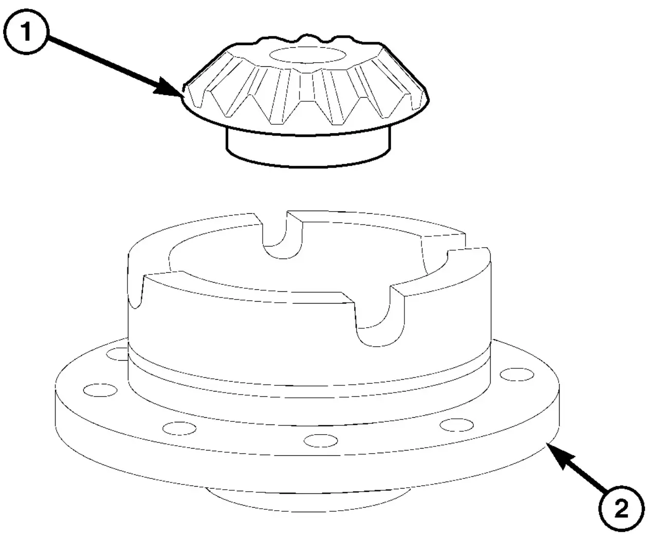
Fig. 42 LOWER SIDE GEAR
- 1 - SIDE GEAR
- 2 - DIFFERENTIAL CASE
(1) Install lower differential side gear (1) and shim (Fig. 42).
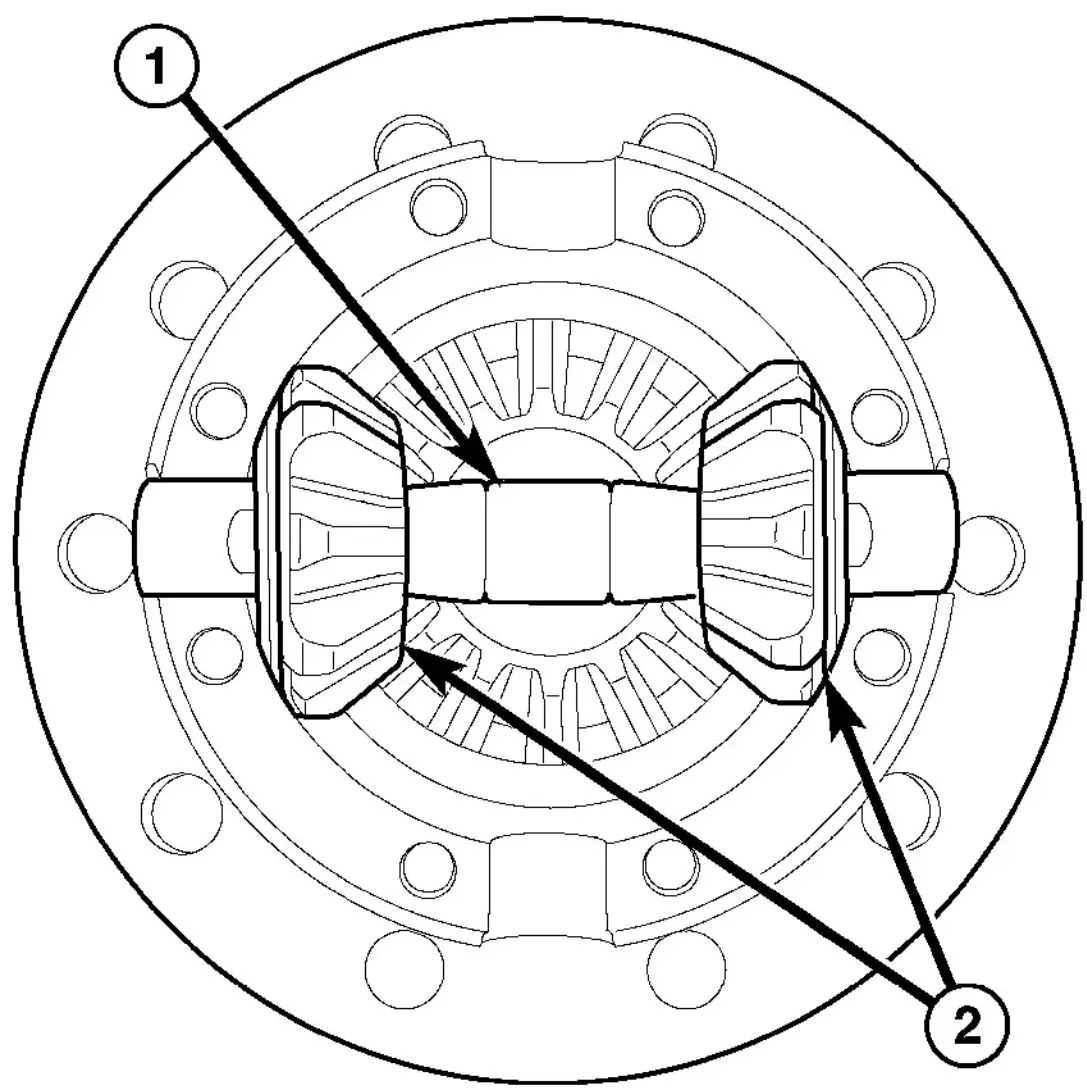
Fig. 43 PINION GEAR SET
- 1 - MATE SHAFT
- 2 - PINION GEARS
(2) Install first differential pinions gears (1) with spherical washers and mate shaft (2) (Fig. 43).
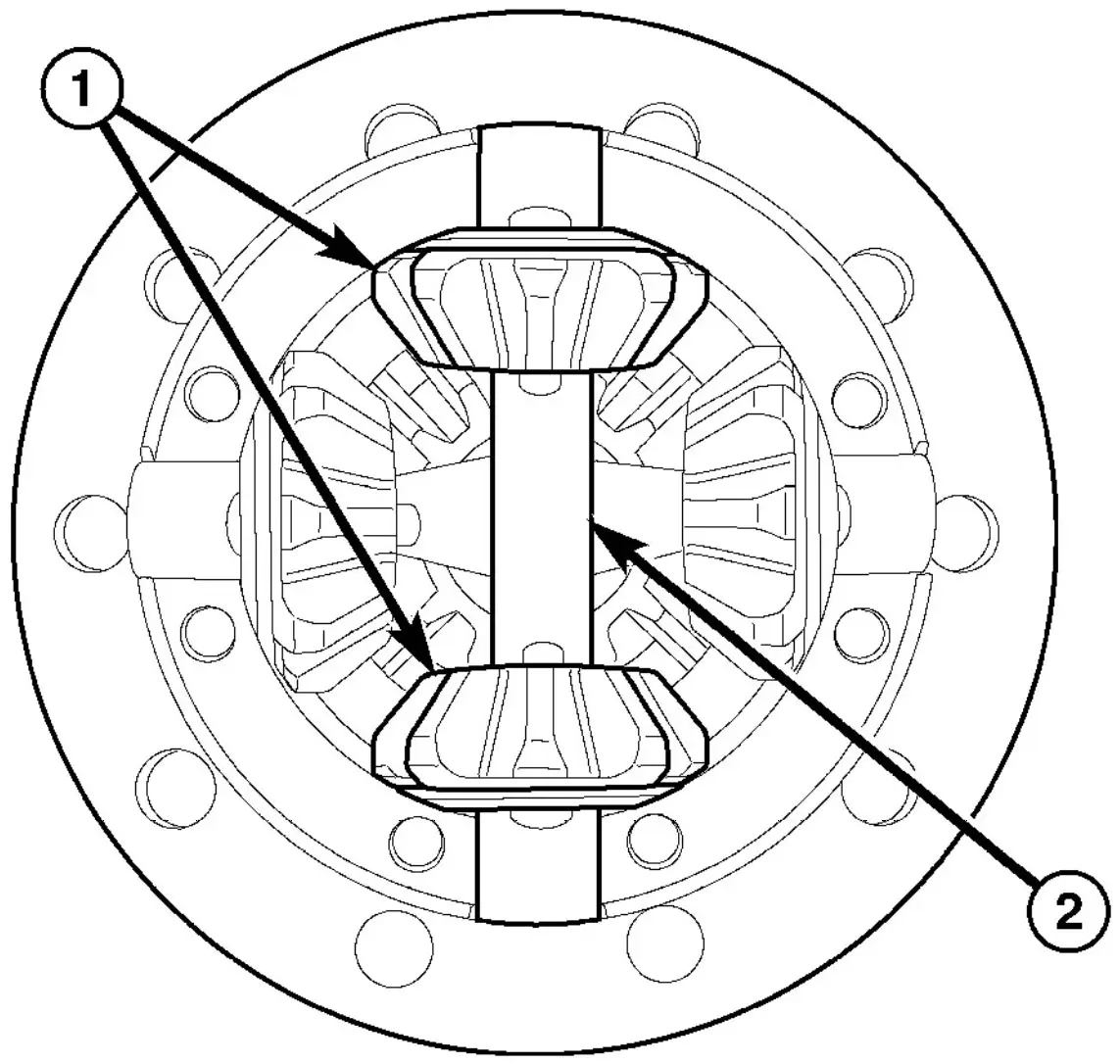
Fig. 44 PINION GEARS
- 1 - PINION GEARS
- 2 - MATE SHAFT
(3) Install second pinion gears (2) with spherical washers and mate shaft (1) (Fig. 44).
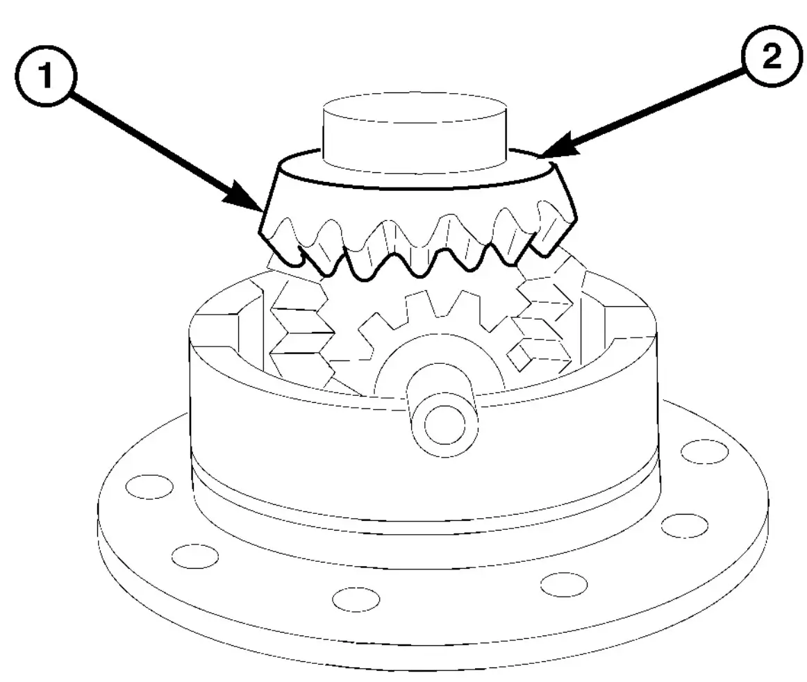
Fig. 45 UPPER SIDE GEAR
- 1 - SIDE GEAR
- 2 - SHIM
(4) Install upper differential side gear (1) and shim (2) (Fig. 45).
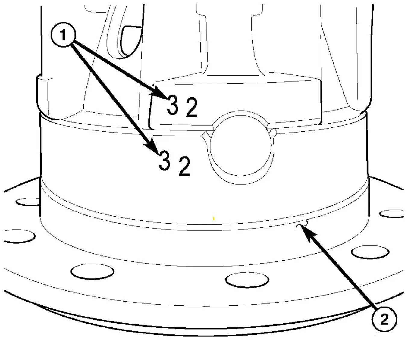
Fig. 46 LOCATION NUMBERS
- 1 - NUMBERS
- 2 - CASE
(5) Install differential cover with location numbers (1) on differential case (2) aligned (Fig. 46).
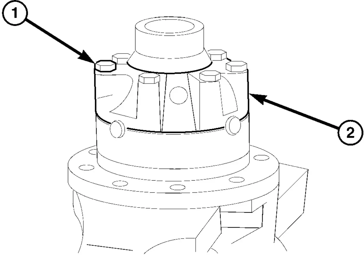
Fig. 47 DIFFERENTIAL COVER
- 1 - BOLTS
- 2 - COVER
(6) Install differential cover (2) bolts (1) and tighten to 45 N·m (33 ft. lbs.) (Fig. 47).
(7) Check torque to rotate the differential gears with Torque Tool 9744 and a torque wrench. Torque should be 20–40 N·m (15-30 ft. lbs.).
DUAL REAR WHEELS DIFFERENTIAL - ASSEMBLY
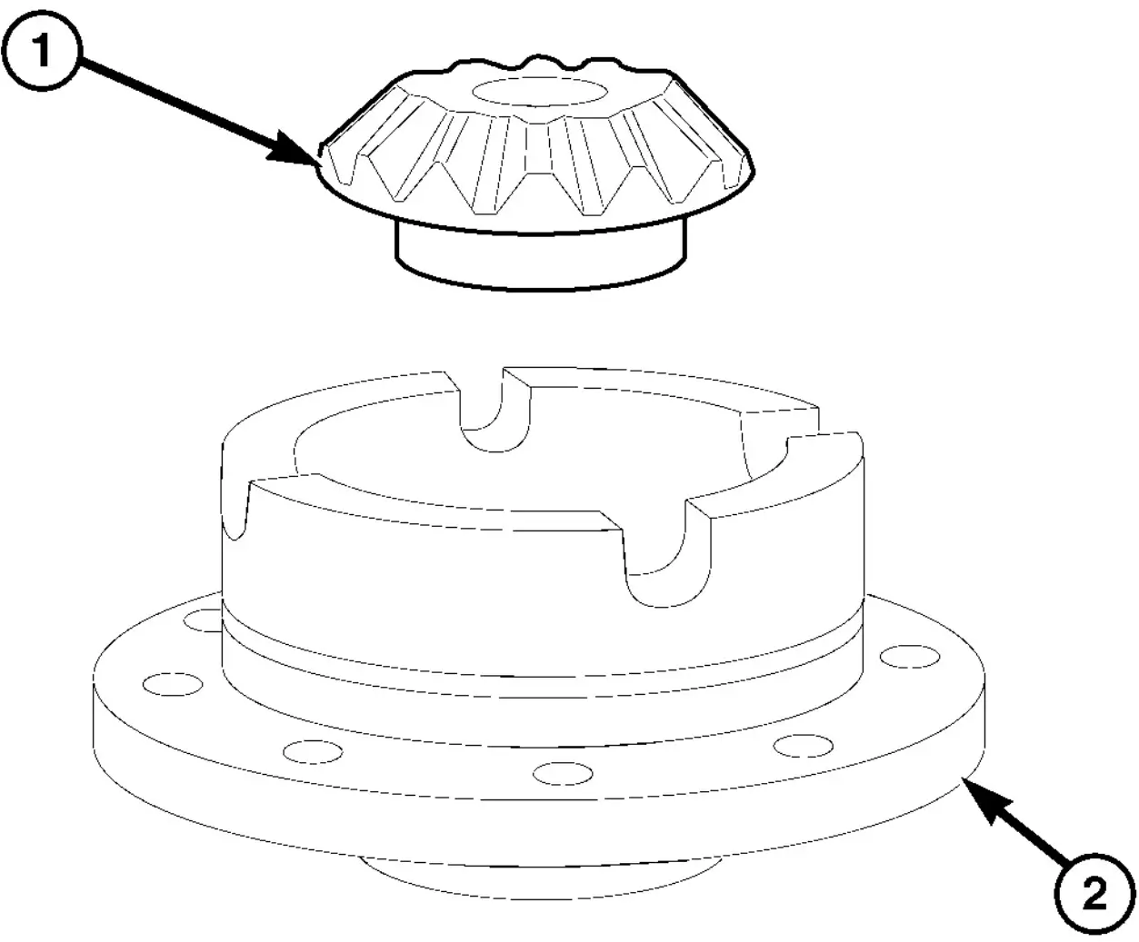
Fig. 48 LOWER SIDE GEAR
- 1 - SIDE GEAR
- 2 - DIFFERENTIAL CASE
(1) Install lower differential side gear (1) and shim (Fig. 48).
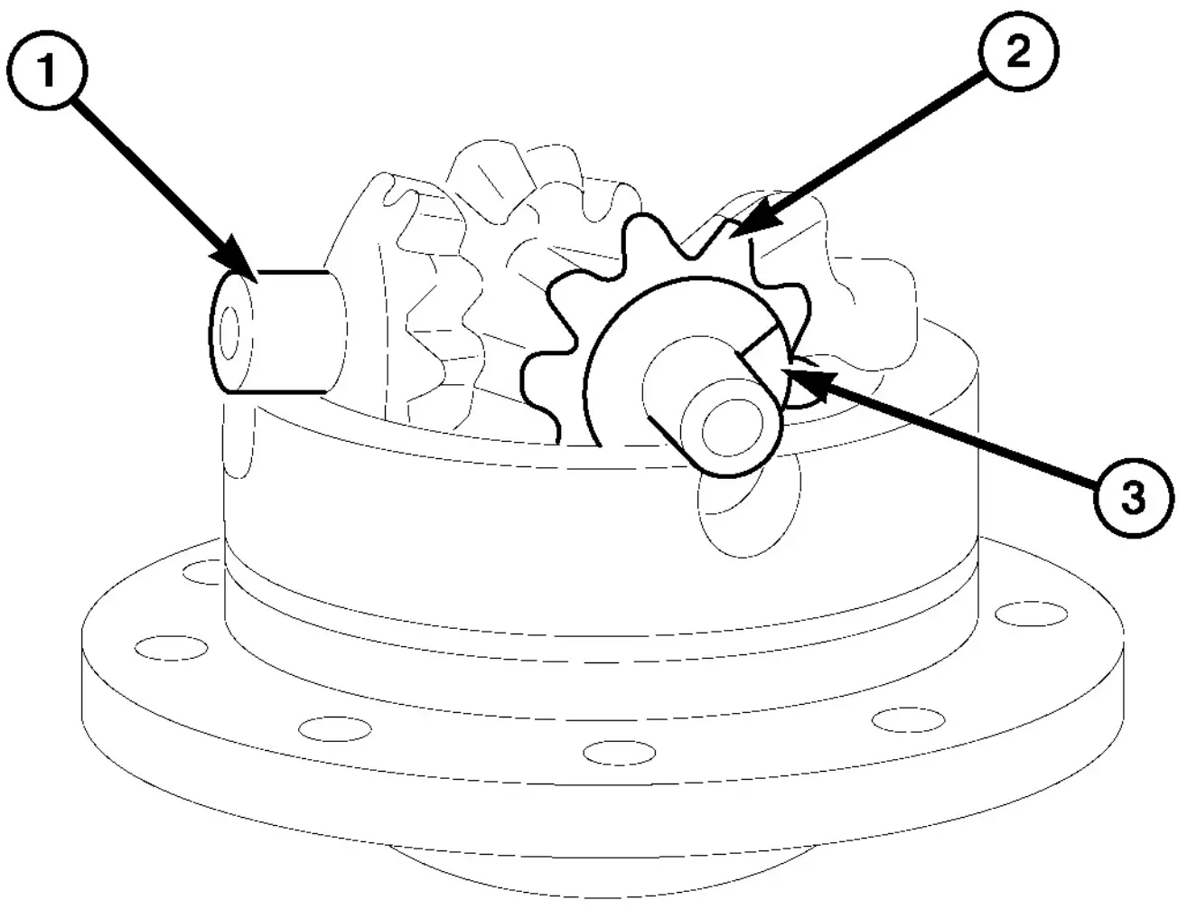
Fig. 49 DIFFERENTIAL PINIONS
- 1 - CROSS SHAFT
- 2 - PINION GEAR
- 3 - WASHER
(2) Install first differential pinions gears (2) with spherical washers (3) and cross shaft (1) (Fig. 49).
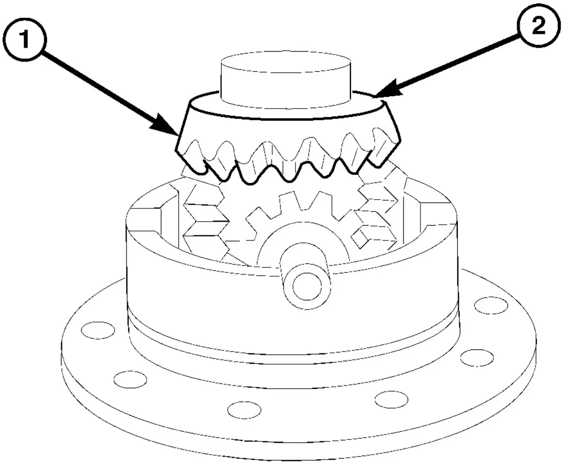
Fig. 50 UPPER SIDE GEAR
- 1 - SIDE GEAR
- 2 - SHIM
(3) Install upper differential side gear (1) and shim (2) (Fig. 50).
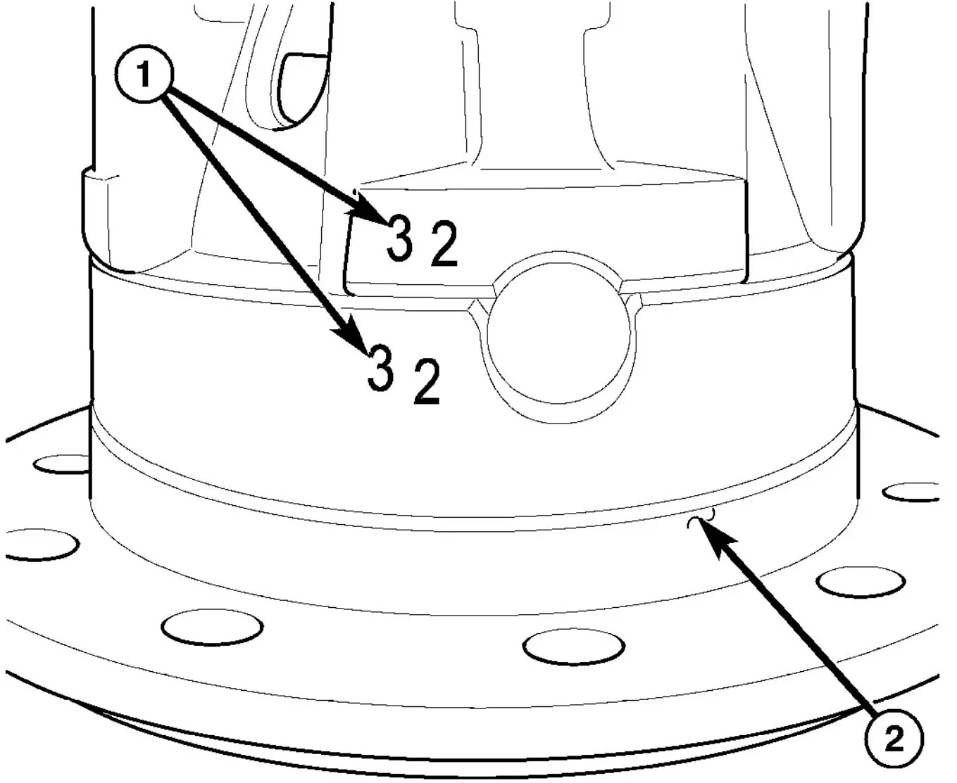
Fig. 51 LOCATION NUMBERS
- 1 - NUMBERS
- 2 - CASE
(4) Install differential cover with location numbers (1) on differential case (2) aligned (Fig. 51).
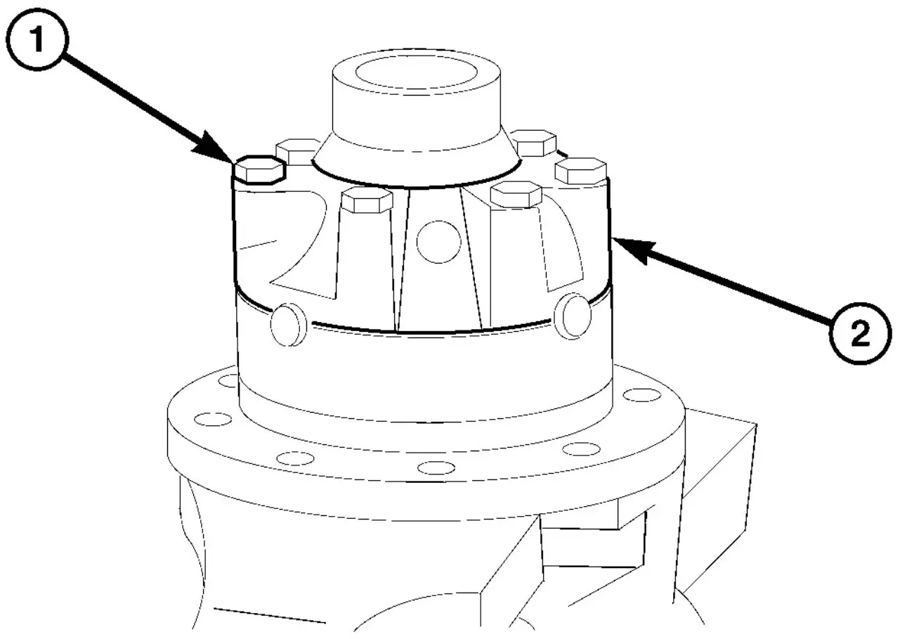
Fig. 52 DIFFERENTIAL COVER
- 1 - BOLTS
- 2 - COVER
(5) Install differential cover (2) bolts (1) and tighen to 45 N·m (33 ft. lbs.) (Fig. 52).
DIFFERENTIAL - INSTALLATION
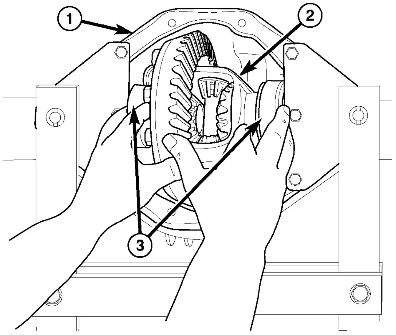
Fig. 53 DIFFERENTIAL INSTALLATION
- 1 - HOUSING
- 2 - DIFFERENTIAL
- 3 - DIFFERENTIAL BEARINGS
(1) Spread the differential housing (1).
(2) Install differential case (2) into the housing (1) with bearings, cups (3) and shims (Fig. 53).
(3) Loosely install differential bearing cap bolts.
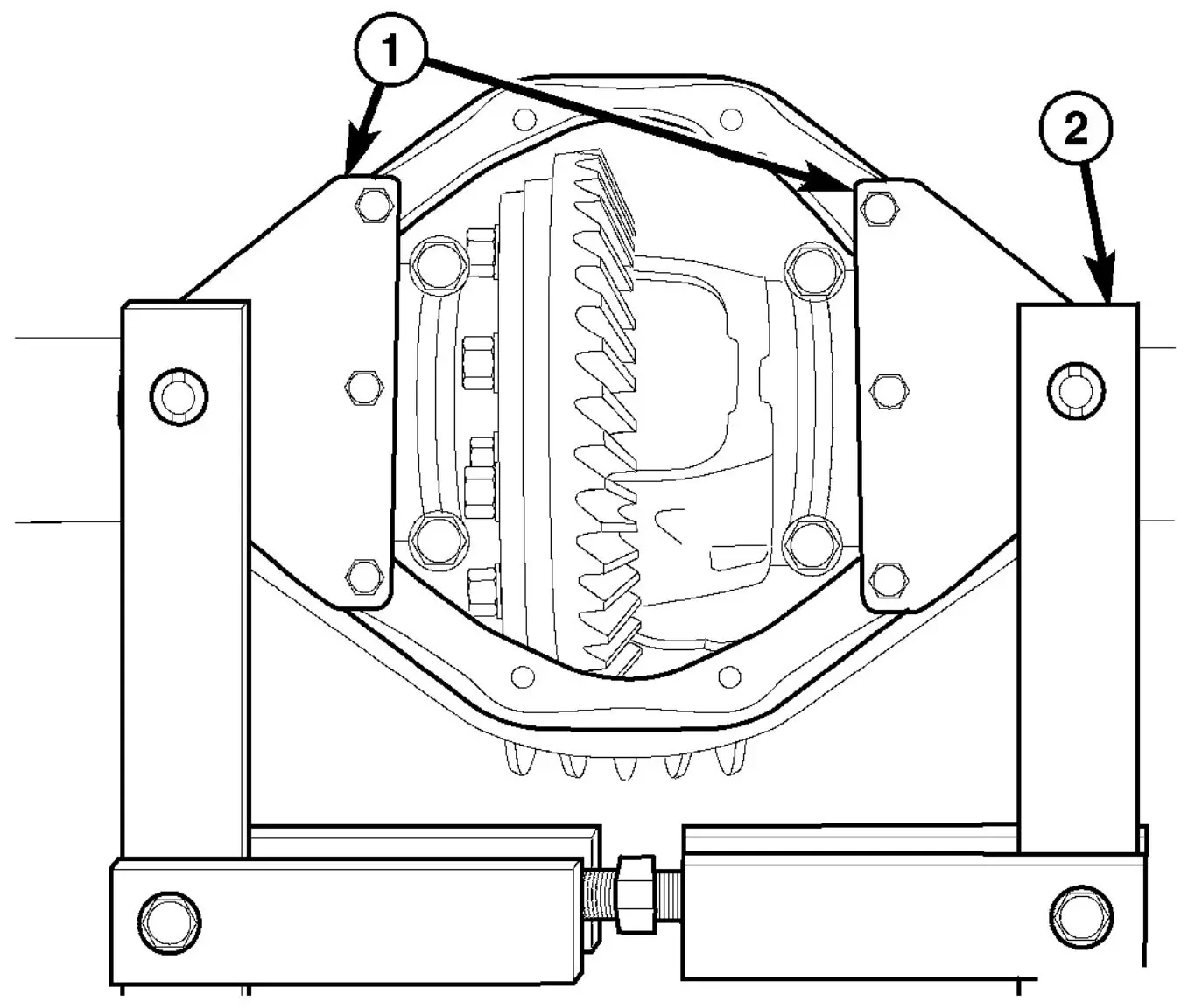
Fig. 54 SPREADER
- 1 - ADAPTERS
- 2 - SPREADER
(4) Remove spreader (2) and adapters (1) from housing (Fig. 54).
(5) Tighten bearing cap bolts to 70 N·m (52 ft. lbs.).
(6) Install axle shafts.
(7) Install differential cover and tighten bolts to 65 N·m (48 ft. lbs.).
(8) Fill differential housing with lubricant.