T1N Sprinter Suspension - Front
Torque Chart
| DESCRIPTION | Nm | Ft. Lbs. | In. Lbs. |
|---|---|---|---|
| Lower Ball Joint To Steering Knuckle | 280 | 206 | --- |
| Strut To Steering Knuckle | 185 | 136 | --- |
| Strut To Body | 100 | 74 | --- |
| Bottom Spring Clamp Plate To Front Axle M12 X 1.5 Bolt | 130 | 96 | --- |
| Bottom Spring Clamp Plate To Front Axle M10 Bolt | 65 | 48 | --- |
| Sway Bar Clamp To The Front Axle | 30 | 22 | --- |
| Hexagon Socket Bolt For Clamping Nut To Adjust Wheel Bearing Play | 12 | 9 | 106 |
| Lower Control Arm To Front Axle Beam | 150 | 110 | --- |
| Stop Plate For the Lower Control Arm | 60 | 44 | --- |
| Outer Tie Rod End Nut | 130 | 96 | --- |
| Outer Tie Rod End Nut Jam Nut | 50 | 37 | --- |
Special Tools
Special Tool Cross-Reference Chart
| MB Tool # | Miller Tool # | Description. | |
|---|---|---|---|
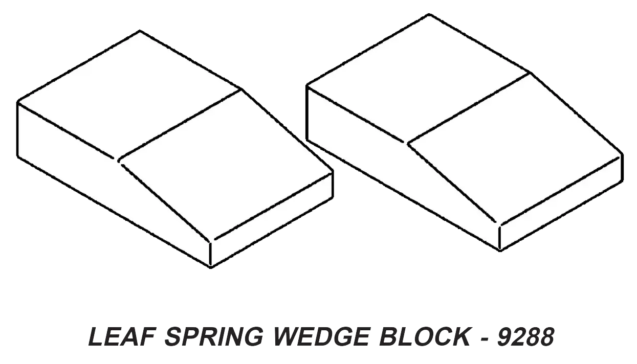
| N/A | 9288 | Leaf Spring Wedge Block |
|
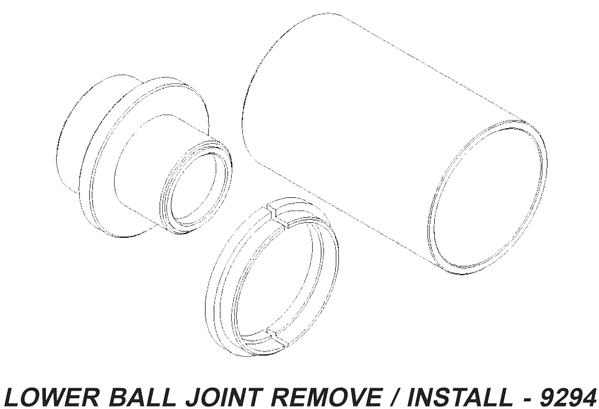
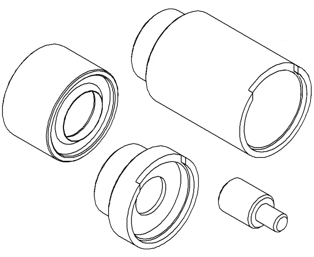
| N/A | 9294 | Lower Ball Joint Remove/installer |
|
| N/A | 9302 | Bushing Remover /installer |
|
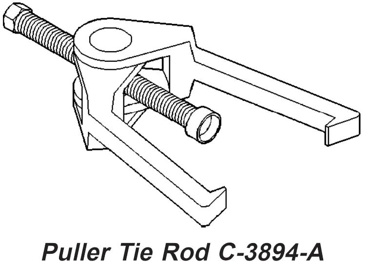
| N/A | C-3894-A | Puller Tie Rod |
|
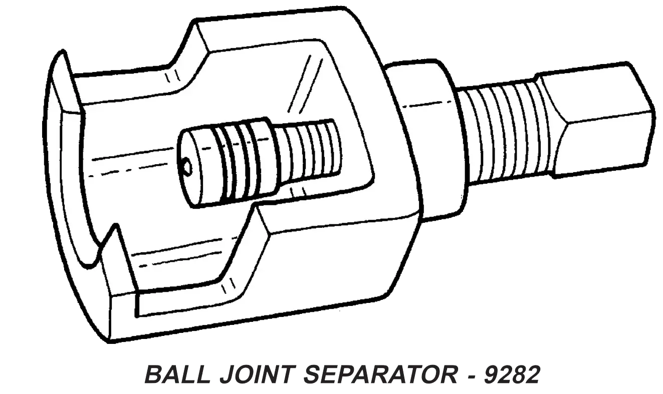
| 730 589 02 33 00 | 9282 | Ball Joint Separator |
|
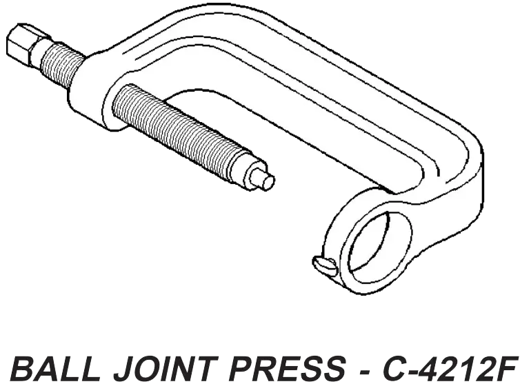
| N/A | C-4212F | Ball Joint Press |
|
Bushing Removal
- Remove the lower control arm (Refer to 2 - SUSPENSION/FRONT/LOWER CONTROL ARM—REMOVAL).
- Install the lower control arm in a vise.
- Install special tool C-4212F (Press) with special tool 9302-1 (Driver) and 9302–3 (Receiver) (Fig. 1).
- Press out the old control arm bushing.
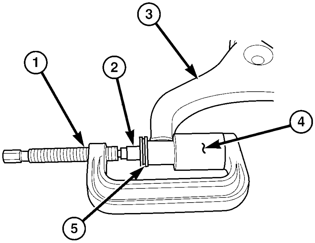
Fig. 1 LCA BUSHING REMOVAL
- SPECIAL TOOL C-4212F (PRESS)
- SPECIAL TOOL 9302-1 (DRIVER)
- LOWER CONTROL ARM
- SPECIAL TOOL 9302-3 (RECEIVER CUP)
- BUSHING
Hub / Bearing Installation
- Install the wheel hub with the tapered roller bearing on the stub axle
- Grease the outer tapered roller bearing thoroughly and push onto the
steering knuckle
Note:The smooth side of the thrust washer must point toward the wheel bearing.
- Install the thrust washer
- Install the clamping nut (Fig. 4). Tighten to 12 N·m (9 ft. lbs.) and then loosen a half of a turn.
- Check for wheel bearing end play. End play should be 0.02- 0.04 mm (0.000787 - 0.00158 in.) (Fig. 3). (Refer to 2 - SUSPENSION/FRONT/HUB / BEARING - DIAGNOSIS AND TESTING)
- Pack the grease cap half with grease and coat at the edge with sealant and install the cap
- Install the disc brake rotor (Refer to 5 - BRAKES/HYDRAULIC/MECHANICAL/ROTORS - INSTALLATION).
- Install the disc brake caliper adapter (Refer to 5 - BRAKES/HYDRAULIC/MECHANICAL/DISC BRAKE CALIPER ADAPTER - INSTALLATION).
- Install the wheel flange ring (if equipped with dual rear wheels) .
- Install the front tire & wheels assembly (Refer to 22 - TIRES/WHEELS/WHEELS - INSTALLATION).
- Lower the vehicle
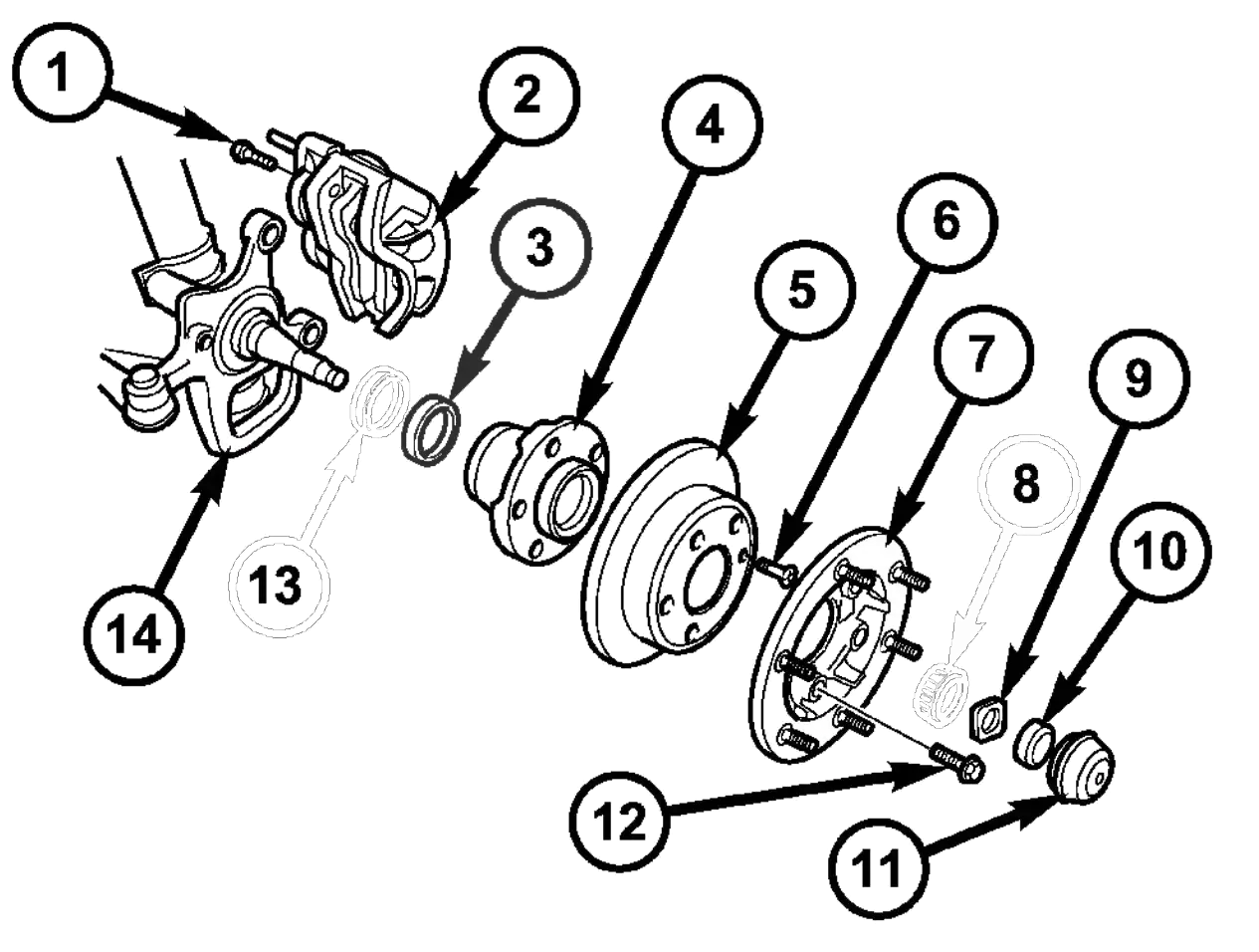
Fig. 5 FRONT WHEEL HUB WITH DUAL REAR WHEELS (DRW)
- ADAPTER BOLT
- DISC BRAKE CALIPER
- INNER BEARING RACE
- WHEEL HUB
- DISC BRAKE ROTOR
- LOCKING BOLT
- WHEEL FLANGE RING
- OUTER BEARING
- THRUST WASHER
- CLAMPING NUT
- GREASE CAP
- WHEEL FLANGE RING MOUNTING BOLT
- GREASE SEAL
- STEERING KNUCKLE
Knuckle Removal
- Raise and support the vehicle.
- Remove the front wheels (Refer to 22 - TIRES/ WHEELS/WHEELS - REMOVAL).
- Remove the disc brake caliper adapter (Refer to 5 - BRAKES/HYDRAULIC/MECHANICAL/DISC BRAKE CALIPER ADAPTER - REMOVAL).
- Remove the hub/bearing (Refer to 2 - SUSPENSION/FRONT/HUB / BEARING - REMOVAL).
- Separate the outer tie rod from the steering knuckle (Fig. 6) using special tool C-3894–A.
- Raise the lower control arm approximately 10 mm using a jack. To eliminate tensile force in the damper strut.
- Remove the ABS sensor from the knuckle by pulling straight out.
- Remove the strut at the knuckle (Fig. 6).
- Separate the lower ball joint from the steering knuckle using special tool 9282 (Fig. 6).
- Remove the steering knuckle from the vehicle (Fig. 6).
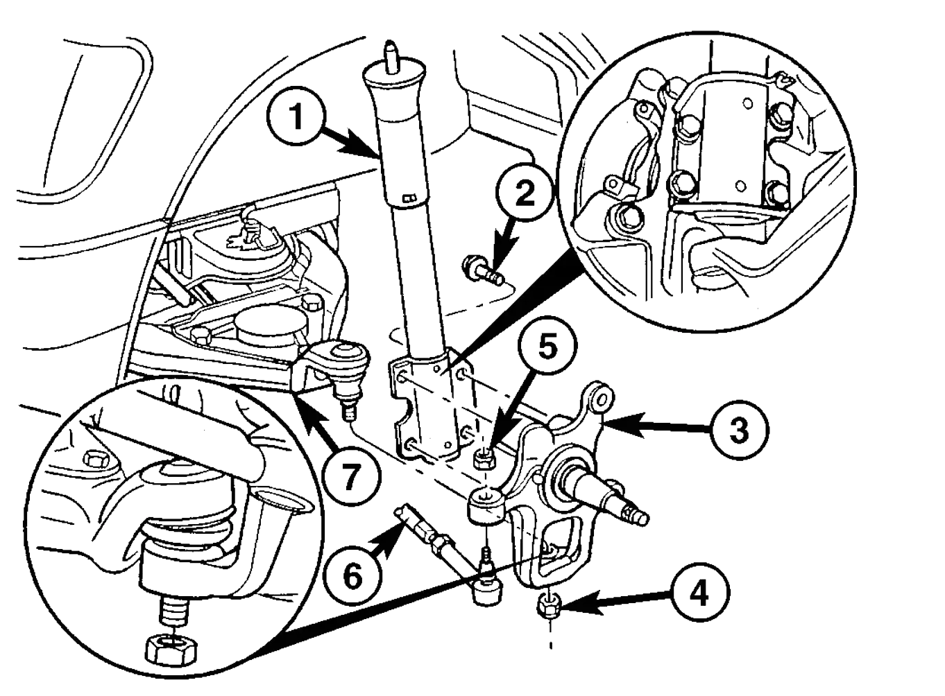
Fig. 6 STEERING KNUCKLE
- STRUT
- STRUT BOLT
- STEERING KNUCKLE
- LOWER BALL JOINT NUT
- OUTER TIE ROD END RETAINING NUT
- INNER TIE ROD END
- LOWER CONTROL ARM
Knuckle Installation
- Install the steering knuckle on the lower ball joint stud (Fig. 6).
- Install the lower ball joint nut (Fig. 6). Tighten to 280 N·m (206 ft. lbs.)
- Install the strut to the steering knuckle (Fig. 6). Tighten to 185 N·m (136 ft. lbs.).
- Install the outer tie rod end to the steering knuckle (Fig. 6) and tighten the nut to 130 N·m (96 ft. lbs.).
- Install the ABS sensor by pushing the sensor all the way into the knuckle, and the sensor will self adjust when the wheel is turned.
- Install the hub/bearing (Refer to 2 - SUSPENSION/FRONT/HUB / BEARING - INSTALLATION).
- Install the disc brake caliper adapter with the brake caliper (Refer to 5 - BRAKES/HYDRAULIC/ MECHANICAL/DISC BRAKE CALIPER ADAPTER - INSTALLATION).
- Install the front wheels (Refer to 22 - TIRES/ WHEELS/WHEELS - INSTALLATION).
- Lower the vehicle
- Check and set toe if necessary (Refer to 2 - SUSPENSION/WHEEL ALIGNMENT - STANDARD PROCEDURE).
Lover Ball Joint Removal
- Raise and support the vehicle.
- Remove the front tire and wheel assembly.
- Remove the front strut (Refer to 2 - SUSPENSION/FRONT/STRUT - REMOVAL).
- Remove the steering knuckle (Refer to 2 - SUSPENSION/FRONT/KNUCKLE - REMOVAL).
- Remove the lower ball joint using special tool 9294-1 (Driver) with 9294-2 (Reciever) and C-4212–F. (Fig. 7).
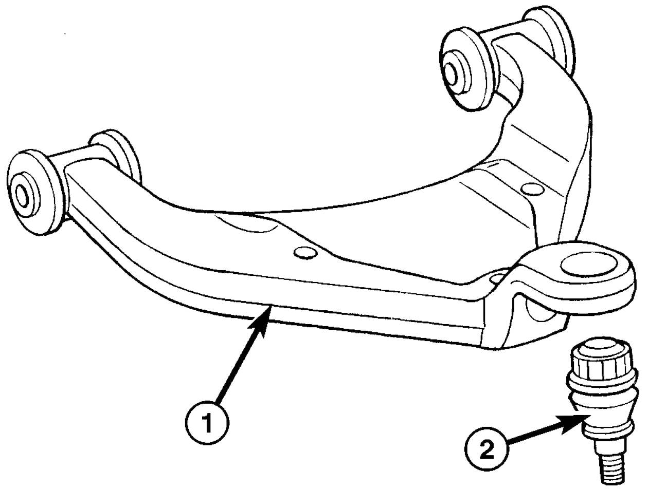
Fig. 7 LOWER BALL JOINT
- LOWER CONTROL ARM
- LOWER BALL JOINT
Lover Ball Joint Installation
- Install the ball joint into the lower control arm using special tool 9294-3 (Installer ring) inserted in 9294-2 (Reciever) and C-4212–F (Fig. 7).
- Install the front strut (Refer to 2 - SUSPENSION/FRONT/STRUT - INSTALLATION).
- Install the steering knuckle (Refer to 2 - SUSPENSION/FRONT/KNUCKLE - INSTALLATION).
- Install the tire and wheel assembly (Refer to 22 - TIRES/WHEELS/WHEELS - INSTALLATION).
- Lower the vehicle.
- Check the front wheel alignment (Refer to 2 - SUSPENSION/WHEEL ALIGNMENT - SPECIFICATIONS).
Lover Control Arm Removal
- Insert spring blocks special tool 9288 between the spring and the spring clamp plates, While the vehicle wheels are on the ground.
- Raise and support the vehicle.
- Remove the front wheels (Refer to 22 - TIRES/ WHEELS/WHEELS - REMOVAL).
- Remove the disc brake caliper adapter (Refer to 5 - BRAKES/HYDRAULIC/MECHANICAL/DISC BRAKE CALIPER ADAPTER - REMOVAL). Hang the caliper. Do not allow brake hose to support the caliper weight.
- Remove the retaining nut holding the tie rod to the steering knuckle (Fig. 8)..
- Seperate the tie rod off the steering knuckle (Fig. 8). using special tool
C-3894–A.
Note:In order to remove tension from the strut, Raise the lower control arm approximately 10 mm with a jack.
- Remove the strut bolts from the steering knuckle (Fig. 8)..
- Remove the stop plate bolts and rotate the plate upwards with the stabilizer link attached (Fig. 8)..
- Lower the lower control arm.
- Remove the lower ball joint nut from the steering knuckle (Fig. 8)..
- Separate the lower ball joint from the knuckle using special tool 9282.
- Remove the lower control arm nuts and bolts from the frame (Fig. 8)..
- Remove the lower control arm
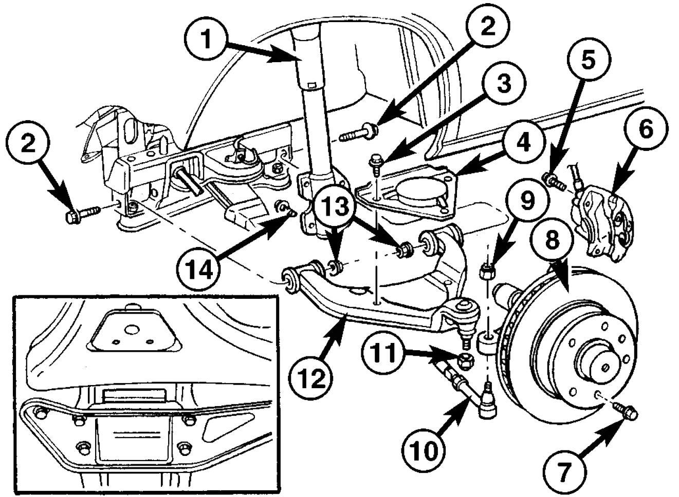
Fig. 8 LOWER CONTROL ARM
- STRUT
- LOWER CONTROL ARM BOLT
- STOP PLATE BOLT
- STOP PLATE
- CALIPER ADPTER BOLT
- DISC BRAKE CALIPE
- LOCKING BOLT
- DISC BRAKE ROTOR
- OUTER TIE ROD END RETAINING NUT
- OUTER TIE ROD END
- LOWER BALL JOINT NUT
- LOWER BALL JOINT
- LOWER CONTROL ARM NUTS
- STRUT BOLT
Lover Control Arm Installation
- Install the lower control arm to the frame. Hand tighten the nuts and bolts.
Note: In order to remove tension from the strut, Raise the lower control arm approximately 10 mm with a jack.
- Install the lower ball joint into the steering knuckle. Tighten to 280 N·m (206 ft. lbs.).
- Install the strut bolts to the steering knuckle (Fig. 8). Tighten to 185 N·m (136 ft. lbs.).
- Install the stop plate (Refer to 2 - SUSPENSION/FRONT/SPRING STOP PLATES - INSTALLATION).
- Lower the lower control arm.
- Attach the tie rod to the steering knuckle (Fig. 8). Tighten the nut to 130 N·m (96 ft. lbs.)
- Install the disc brake caliper adapter (Refer to 5 - BRAKES/HYDRAULIC/MECHANICAL/DISC BRAKE CALIPER ADAPTER - INSTALLATION) (Fig. 8).
- Install the front tire & wheel assembly (Refer to 22 - TIRES/WHEELS/WHEELS - INSTALLATION).
- Lower the vehicle.
- Remove the spring blocks between the spring and the spring clamp plates, While the vehicles wheels are on the ground.
- Roll the vehicle approximately 1 mm forwards and the backwards, and rock firmly.
- Tighten the lower control arm nuts and bolts to the frame to 150 N·m (110 ft. lbs.) (Fig. 8).
- Apply brake to actuate brake pressure.
Spring Removal
- To do this next step the vehicle must be on the ground. Remove the front and rear bolts on the left and right spring clamp plates (Fig. 9).
- Raise and support the vehicle.
- Remove the front wheels.
- Remove the brake caliper adapter (Refer to 5 - BRAKES/HYDRAULIC/MECHANICAL/DISC BRAKE CALIPER ADAPTER - REMOVAL). Do not allow the caliper to hang by the hose, support the caliper accordingly.
- Remove the ABS sensor from the mounting bore in the steering knuckle (Fig. 9).
- Remove the outer tie rod retaining nut and separate the tie rod from the
knuckle (Fig. 9) using special tool C-3894–A.
Note: In order to remove tension from the strut, Raise the lower control arm approximately 10 mm with a jack.
- Remove the strut bolts from the steering knuckle.
- Remove both stop plate bolts and rotate the plates upwards with the stabilizer link attached.
- Lower the lower control arm.
- Remove the lower ball joint nut from the steering knuckle.
- Separate the lower ball joint from the knuckle using special tool 9282.
- Remove the lower control arm nuts and bolts from the frame.
- Remove the lower control arm from the frame (Fig. 9).
Note: To avoid damaging the transverse leaf spring, cushion the pad on the jack accordingly.
- Support the transverse leaf spring in the center with a jack.
- Remove the left and right spring clamp plates (Refer to 2 -
SUSPENSION/FRONT/SPRING CLAMP PLATES - REMOVAL) (Fig. 9).
Note: The upper spring blocks between the engine cradle and the spring are color coded, Make sure not to mix the blocks per sides. The blocks are different in sizes to accommodate the weight of the vehicle and driver in order for the vehicle to sit level.
- Lower the jack and remove the transverse leaf spring towards the side.
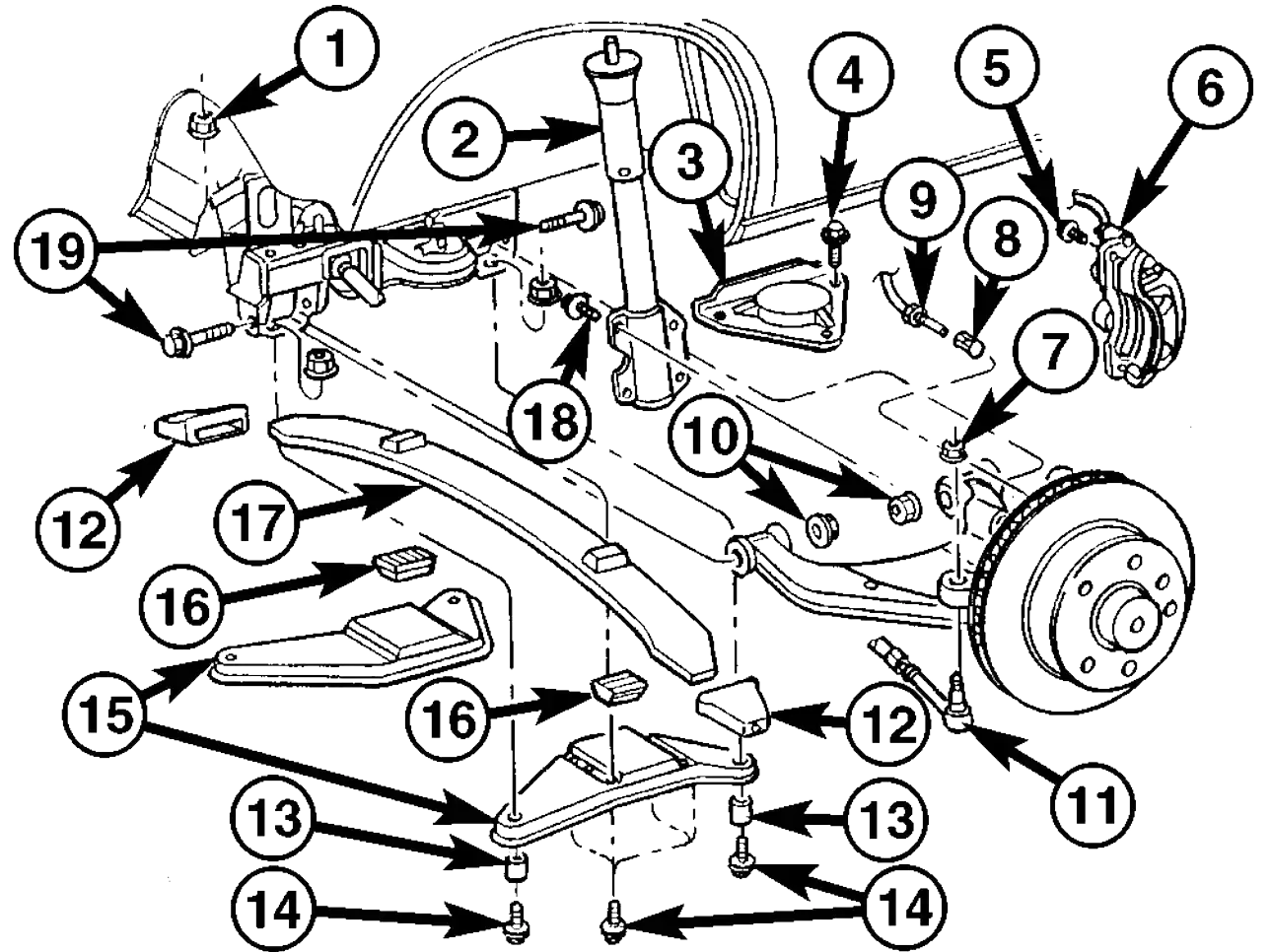
Fig. 9 FRONT SPRING
- NUT
- STRUT
- STOP PLATE
- STOP PLATE BOLT
- CALIPER ADAPTER BOLT
- DISC BRAKE CALIPER
- OUTER TIE ROD END NUT
- ABS SENSOR
- SPEED SENSOR
- LOWER CONTROL ARM RETAINING NUTS
- OUTER TIE ROD END
- RUBBER SPRING MOUNT
- SHEAR BUSHING
- SPRING CLAMP PLATE BOLT
- SPRING CLAMP PLATE
- LOWER RUBBER SPRING MOUNT
- SPRING
- STRUT BOLTS
- LOWER CONTROL ARM BOLTS
Spring Installation
Note:
To avoid damaging the transverse leaf spring, cushion the pad on the jack
accordingly.
Note:
Hand tighten all bolts until vehicle is on the ground, unless the bushings may
become distorted.
Note:
The height blocks between the engine cradle and the spring are color coded, Make
sure not to mix the blocks per sides. The blocks are different in sizes to
accommodate the weight of the vehicle and driver in order for the vehicle to sit
level.
- Install the transverse leaf spring in the center with a jack with all the rubber mounts attached.
- Install the lower control arm to the frame (Fig. 9).
- Install the knuckle on the lower ball joint.
- Raise the lower control arm approximately 10 mm with a jack.
- Install both stop plate bolts to the lower control arm.
- Install the strut bolts to the steering knuckle.
- Reinstall the tie rod to the steering knuckle (Fig. 9). Tighten to 150 N·m (110 ft. lbs.)
- Install the ABS sensor all the way into the steering knuckle, the sensor will adjust automatically when the vehicle is moved (Fig. 9).
- Install the disc brake caliper adapter (Fig. 9). Tighten to 170 N·m (125 ft. lbs.)
- Install the front wheels.
- Lower the vehicle.
- Install the spring clamp plates (Fig. 9). Tighten (M-10 bolts) to 65 N·m (48 ft. lbs.) (M-12 bolts) to 130 N·m (96 ft. lbs.).
- Roll the vehicle approximately 1 mm forwards and the backwards, and rock firmly.
- Tighten the nuts on the lower control arm to the frame to 150 N·m (110 ft. lbs.).
- Apply brake to actuate brake pressure.
Spring Clamp Plates Removal
- Raise and support the vehicle.
- Install a jack under the lower ball joint and lower the weight of the vehicle enough to allow a wrench between the lower control arm and the bracket tighten the nut.
- Remove the front and rear bolts to the spring clamp plates.
- Remove the four inner retaining bolts and nuts.
- Remove the spring clamp plate and rubber block.
- Remove the shear bushings from the front and rear bolts.
Spring Clamp Plates Installation
- Install a jack under the lower ball joint and lower the weight of the vehicle enough to allow a wrench between the lower control arm and the bracket tighten the nut.
- Fit one spring clamp plate together with the lower spring rubber block.
- Install the bolt with the shear bushing on the rear mounting, Do not tighten yet.
- Install the four retaining bolts for the spring clamp plate. Tighten to 65 N·m (48 ft.lbs.).
- Align the holes for the front clamp plate joint using a suitable drift (shear bushing not installed).
- Remove the alignment drift.
- Insert the shear bushing and retaining bolt into the hole and tighten to 130 N·m (96 ft.lbs.).
- Remove the jack and lower the vehicle.
Spring Top Plates Removal
- Raise and support the vehicle.
- Remove the tire and wheel assembly.
- Remove the lower end of the stabilizer link from the stop plate.
- Remove the three bolts retaining the spring stop plate from the lower control arm.
Spring Top Plates Installation
- Install the spring stop plate to the lower control arm. Tighten the bolts to 60 N·m (44 ft. lbs.).
- Install the stabilizer link to the spring stop plate.
- Install the tire and wheel assembly.
- Lower the vehicle.
Stabilizer Bar Description
The bar extends across the front underside of the chassis and connects to the frame crossmember. The ends of the bar mount to the lower suspension arm. All mounting points of the stabilizer bar are isolated by bushings (Fig. 10).
Operation
The stabilizer bar is used to minimize vehicle front sway during turns. The bar helps to maintain a flat attitude to the road surface.
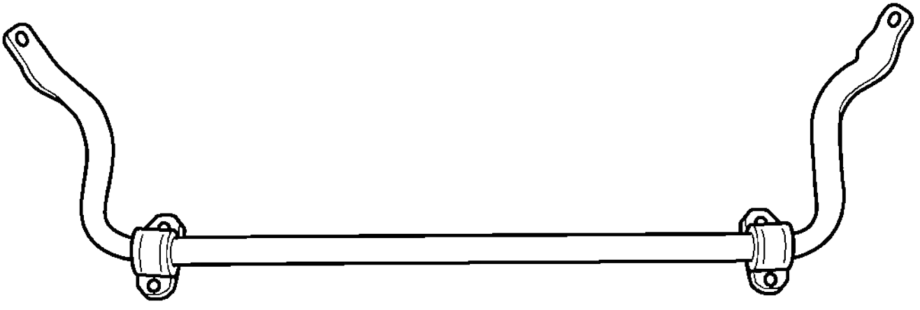
Fig. 10 STABILIZER BAR
Stabilizer Bar Removal
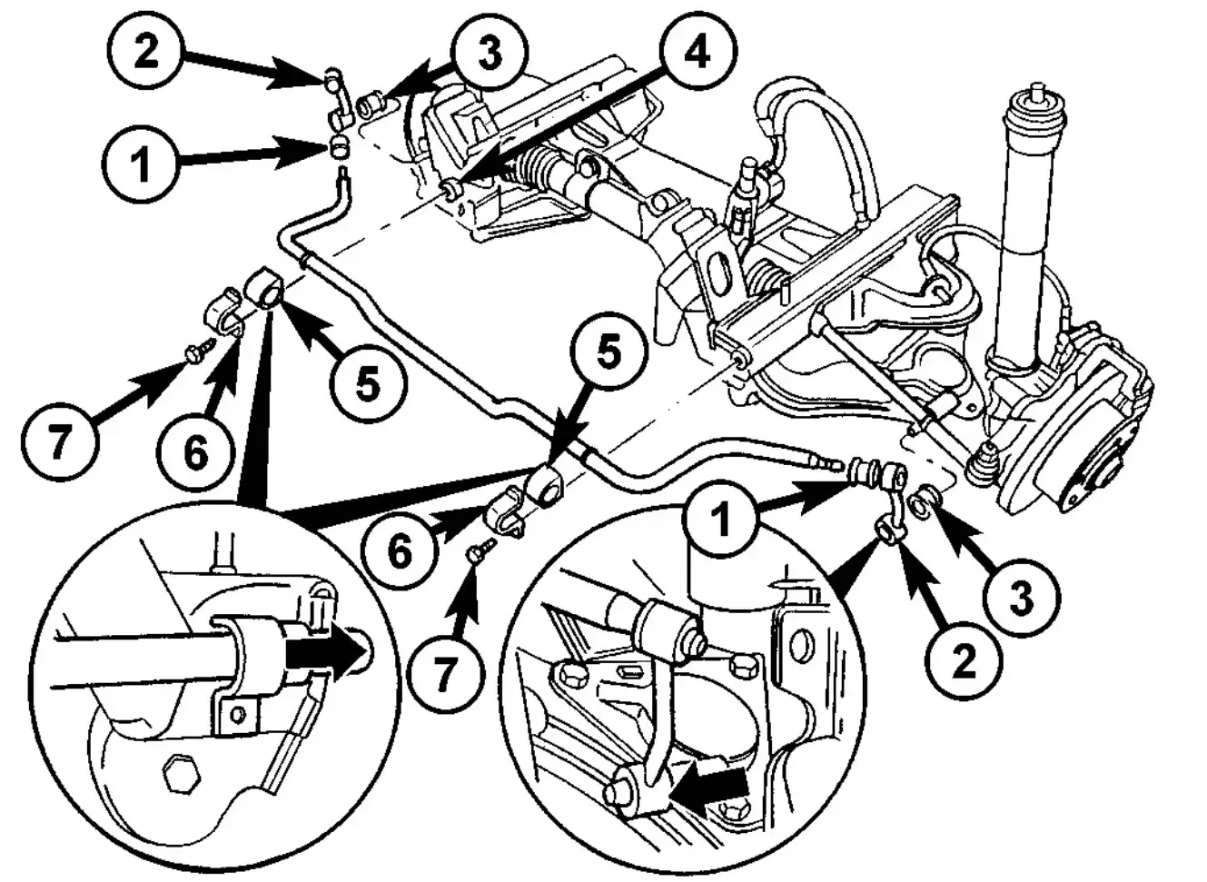
Fig. 11 STABILIZER BAR
- RUBBER MOUNT
- STABILIZER LINK
- RUBBER MOUNT
- NUT
- RUBBER MOUNT
- CLAMP BRACKET
- BOLT
Stabilizer Bar Installation
- Install a mild detergent soap the to rubber bushings on the stabilizer link.
- Install the stabilizer links onto the stabilizer bar and spring stop plate by pushing on the link.
- Lower the vehicle.
Strut Removal
- On the drivers side remove the floor covering off to the side.
- On the passengers side take off the cover for the tools.
- Remove the cover for the upper strut mounting (Fig. 12).
- Remove the nut on the upper strut mounting (Fig. 12).
- Raise and support the vehicle.
- Remove the front wheels.
- Raise the lower control arm approximately 10 mm with a jack to remove the tension from the strut.
- Remove the strut from the steering knuckle (Fig. 12).
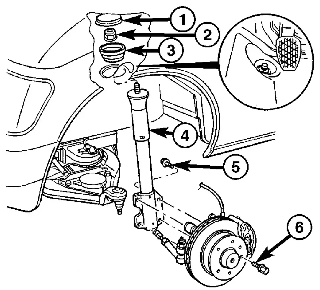
Fig. 12 STRUT
- COVER
- NUT
- RUBBER MOUNT
- STRUT
- STRUT BOLT
- LOCKING BOLT
Strut Installation
Note:Hand tighten
the strut upper mounting nut
until the vehicle is on the ground, otherwise the
bushings may become distorted.
- Install strut to the steering knuckle (Fig. 12). Tighten to 185 N·m (136 ft. lbs.).
- Raise the lower control to install the upper part of the strut into the footwell. Tighten to 100 N·m (74 ft. lbs.).
- Install wheels (Refer to 22 - TIRES/WHEELS/ WHEELS - INSTALLATION).
- Lower the vehicle.
- Install the nut covers (Fig. 12)
- Refit the floor covering and the tool cover.
Sprinter T1N World
2026 All Rights Reserved.
v1.7.8