T1N Sprinter Suspension - Rear
Description
The rear suspension comprises:
- Shock Absorbers
- Jounce Bumpers
- Stabilizer Bar
- Leaf Springs
- Drive Axle
DIAGNOSIS AND TESTING - SPRING AND SHOCK
A knocking or rattling noise from a shock absorber may be caused by movement between mounting bushings and metal brackets or attaching components. These noises can usually be stopped by tightening the attaching nuts. If the noise persists, inspect for damaged and worn bushings, and attaching components. Repair as necessary if any of these conditions exist.
A squeaking noise from the shock absorber may be caused by the hydraulic valving and may be intermittent. This condition is not repairable and the shock absorber must be replaced.
The shock absorbers are not refillable or adjustable. If a malfunction occurs, the shock absorber must be replaced. To test a shock absorber, hold it in an upright position and force the piston in and out of the cylinder four or five times. The action throughout each stroke should be smooth and even.
The spring eye and shock absorber bushings do not require any type of lubrication. Do not attempt to stop spring bushing noise by lubricating them. Grease and mineral oil-base lubricants will deteriorate the bushing rubber.
If the vehicle is used for severe, off-road operation, the springs should be examined periodically. Check for broken and shifted leafs, loose and missing clips, and broken center bolts. Refer to Spring and Shock Absorber Diagnosis chart for additional information.
SPRING AND SHOCK ABSORBER
| Condition | Possible Causes | Correction |
|---|---|---|
| Spring Sags |
|
|
| Spring Noise |
|
|
| Shock Noise |
|
|
Torque Chart
| DESCRIPTION | Nm | Ft. Lbs. | In. Lbs. |
|---|---|---|---|
| Sway Bar Link | 95 | 60 | --- |
| Sway Bar Clamp To Axle (SRW) | 25 | 18 | --- |
| Sway Bar Clamp To Axle (DRW) | 70 | 52 | --- |
| Rear Spring To Front Spring Bracket (SRW) | 95 | 70 | --- |
| Rear Spring To Front Spring Bracket (DRW) | 185 | 136 | --- |
| Rear Spring To Rear Spring Bracket (SRW) | 85 | 63 | --- |
| Rear Spring To Rear Spring Bracket (DRW) | 185 | 136 | --- |
| Spring Shackle To Rear Spring Bracket (SRW) | 90 | 66 | --- |
| Spring Shackle To Rear Spring Bracket (DRW) | 185 | 136 | --- |
| U-Bolt To Spring Plate & Axle (SRW&DRW) | 170 | 125 | --- |
| Lower Shock Mounting To Rear Axle M12 X 1.5 Bolt | 70 | 52 | --- |
| Lower Shock Mounting To Rear Axle M14 X 1.5 Bolt (SRW&DRW) | 110 | 81 | --- |
| Upper Shock Mounting To Frame (SRW) | 80 | 59 | --- |
| Upper Shock Mounting To Frame (DRW) | 140 | 103 | --- |
DIAGNOSIS AND TESTING - SHOCK
A knocking or rattling noise from a shock absorber may be caused by movement between mounting bushings and metal brackets or attaching components. These noises can usually be stopped by tightening the attaching nuts. If the noise persists, inspect for damaged and worn bushings, and attaching components. Repair as necessary if any of these conditions exist.
A squeaking noise from the shock absorber may be caused by the hydraulic valving and may be intermittent. This condition is not repairable and the shock absorber must be replaced.
The shock absorbers are not refillable or adjustable. If a malfunction occurs, the shock absorber must be replaced. To test a shock absorber, hold it in an upright position and force the piston in and out of the cylinder four or five times. The action throughout each stroke should be smooth and even.
The shock absorber bushings do not require any type of lubrication. Do not attempt to stop bushing noise by lubricating them. Grease and mineral oilbase lubricants will deteriorate the bushing.
Shock Removal
- Raise and support the vehicle.
- Remove the shock absorber bolt from the rear axle (Fig. 1).
- Unsnap the clip for the ALB lever (left hand side) (Fig. 1).
- Remove the ALB lever from the upper shock bolt/stud (Fig. 1).
- Remove the shock absorber bolt from the frame side (Fig. 1).
- Remove the shock absorber (Fig. 1).
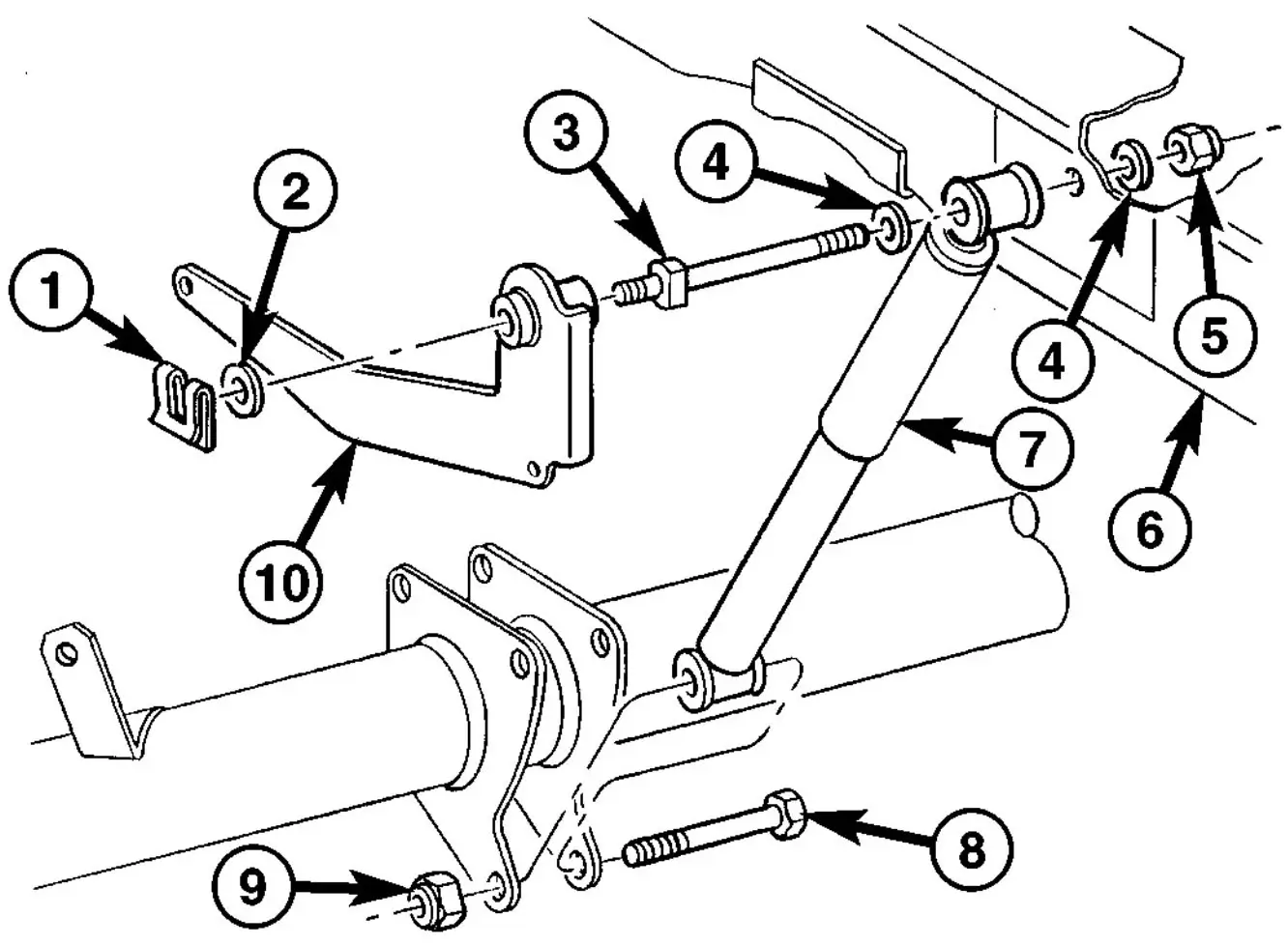
Fig. 1 SHOCK ABSORBER (LEFT SIDE SHOWN)
- CLIP
- WASHER
- MOUNTING STUD/BOLT
- WASHER
- NUT
- FRAME
- SHOCK ABSORBER
- BOLT
- NUT
- ALB LEVER
Shock Installation
- Install the shock absorber (Fig. 1).
- Install the shock absorber bolt to the frame side (Fig. 1) Tighten to 80 N·m (59 ft.lbs.) for (SRW) or Tighten to 140 N·m (103 ft.lbs.) for (DRW).
- Install the ALB lever to the upper shock bolt/ stud (left hand side only) (Fig. 1).
- Snap the clip for the ALB lever (Fig. 1).
- Install the shock absorber bolt to the rear axle (Fig. 1) Tighten to 70 N·m (52 ft.lbs.) for (M12X1.5 bolt) or Tighten to 110 N·m (81 ft.lbs.) for (M14X1.5 bolt).
- Lower the vehicle.
Spring Description
The rear suspension system uses a multi-leaf springs and a solid drive axle. The forward end of the springs are mounted to the body rail hangers through rubber bushings. The rearward end of the springs are attached to the body by the use of shackles. The spring and shackles use rubber bushings.
Operation
The springs control ride quality and maintain vehicle ride height. The shackles allow the springs to change their length as the vehicle moves over various road conditions.
Spring Removal - (SRW)
- Raise and support the vehicle.
- Support the rear axle.
- Remove the U-bolt and spring plate (Fig. 2).
- Remove the spring from the front spring bracket (Fig. 2).
- Remove the rear spring with the spring shackle from the spring bracket (Fig. 2).
- Lower the rear axle and remove the rear spring.
- Remove the spring shackle from the spring (if needed) (Fig. 2)
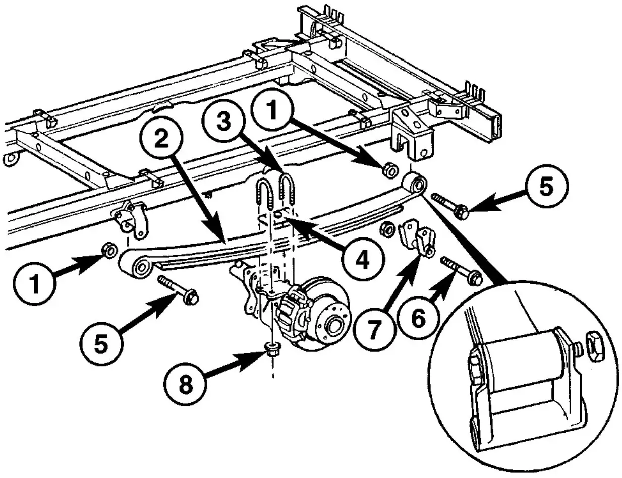
Fig. 2 REAR LEAF SPRING WITH SINGLE REAR WHEELS
- NUT
- LEAF SPRING
- U-BOLTS
- PLATE
- SPRING BOLT
- SHACKLE BOLT
- SPRING SHACKLE
- U-BOLT NUTS
Spring Removal - (DRW)
- Raise and support the vehicle.
- Support the rear axle.
- Remove the U-bolt and spring plate (Fig. 3).
- Remove the spring from the front spring bracket (Fig. 3).
- Remove the rear spring with the spring shackle from the spring bracket (Fig. 3)
- Lower the rear axle and remove the rear spring.
- Remove the spring shackle from the spring (if needed) (Fig. 3).
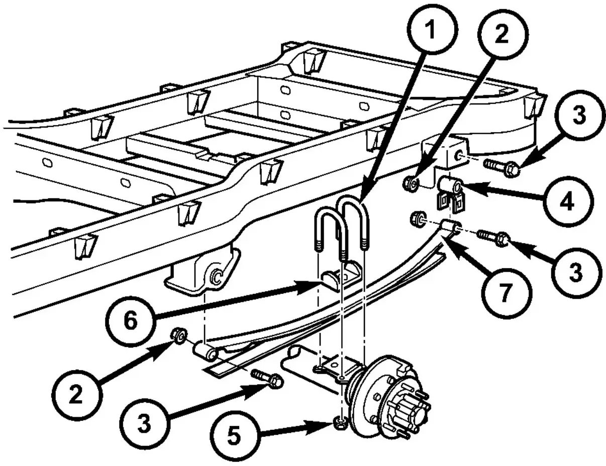
Fig. 3 REAR LEAF SPRING WITH DUAL REAR WHEELS
- U-BOLTS
- NUT
- BOLT
- SPRING SHACKLE
- U-BOLT MOUNTING NUT
- U-BOLT BRACKET ALIGNING PLATE
- LEAF SPRING
Spring Installation - (SRW)
- Install the spring shackle to the spring (if removed) (Fig. 2). Tighten to 90 N·m (66 ft. lbs.).
- Install the spring to the front spring bracket (Fig. 2). Tighten to 95 N·m (70 ft. lbs.).
- Install the spring to the rear spring bracket (Fig. 2). Tighten to 85 N·m (63 ft. lbs.).
- Raise the rear axle and attach the spring plate and U-bolts (Fig. 2). Tighten to 170 N·m (125 ft. lbs.).
- Lower the vehicle.
Spring Installation - (DRW)
- Install the spring shackle to the spring (if removed) (Fig. 3). Tighten to 185 N·m (136 ft. lbs.).
- Install the spring to the front spring bracket (Fig. 3). Tighten to 185 N·m (136 ft. lbs.).
- Install the spring to the rear spring bracket (Fig. 3). Tighten to 185 N·m (136 ft. lbs.).
- Raise the rear axle and attach the spring plate and U-bolts (Fig. 3). Tighten to 170 N·m (125 ft. lbs.).
- Lower the vehicle.
Spring Shackle Removal
- Raise and support the vehicle.
- Support the rear axle.
- Remove both the rear spring shackles from the spring bracket.
- Lower the rear axle and remove the rear spring shackle from the spring.
Spring Shackle Installation
- Install the spring shackle to the spring. Tighten to 90 N·m (66 ft. lbs.).
- Raise the rear axle while installing the spring shackle to the spring bracket. Tighten to 85 N·m (63 ft. lbs.).
- Lower the vehicle.
STABILIZER BAR Removal
.webp)
Fig. 4 SWAY BAR WITH SINGLE REAR WHEELS (SRW)
- M12 NUT
- BUSHING
- SWAY BAR LINK
- M12 BOLT
- SWAY BAR
- CLAMP
- M8 BOLT
- BRACKET
- FOUR POINT NUT M8
- WASHER
- M8 NUT
- BUSHING
- MOUNT
STABILIZER BAR Installation
- Install the stabilizer bar to the axle.
- Install the stabilizer bar clamps and bracket, center the bar then tighten to 25 N·m (18ft. lbs.) (SRW) (Fig. 4) or Tighten to 70 N·m (52 ft. lbs.) for (DRW) (Fig. 5).
- Install the stabilizer bar to the stabilizer links and tighten to 95 N·m (60 ft. lbs.) (Fig. 4) or (Fig. 5).
- Lower the vehicle.
.webp)
Fig. 5 SWAY BAR WITH DUAL REAR WHEELS (DRW)
- STABILIZER LINK
- SWAY BRA BOLT
- SWAY BAR NUT
- SWAY BAR
- RUBBER MOUNT
- SWAY BAR CLAMP
- CLAMP MOUNTING BOLTS
STABILIZER Link Removal
- Raise and support the vehicle.
- Remove the stabilizer links at the bar (Fig. 4).
- Remove the stabilizer link at the frame.
STABILIZER Link Installation
- Install the stabilizer bar to the stabilizer links and tighten to 95 N·m (60 ft. lbs.) (Fig. 4).
- Lower the vehicle.
- Install the stabilizer link to the frame. Tighten to 95 N·m (60 ft. lbs.).