T1N Sprinter Differential & Driveline - Pinion
Pinion Seal Removal
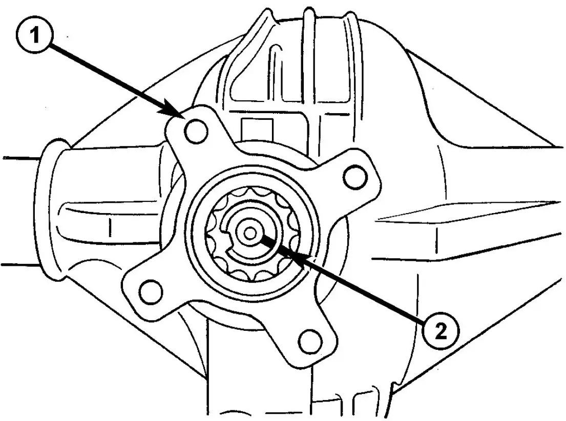
Fig. 57 COLLARED NUT
- 1 - PINION FLANGE
- 2 - COLLARED NUT
(1) I Remove wheels.
(2) Push back brake pads and release hand brake.
(3) Drain rear axle oil.
(4) Remove propeller shaft.
(5) Spin pinion flange by hand and check axial play of bearing.
(6) Measure and record torque to rotate the pinion.
(7) Mark pinion position to pinion flange (1) (Fig. 57).
(8) Unlock collared nut
(9) Hold pinion flange (1) with Flange Wrench C-3281 and remove nut.
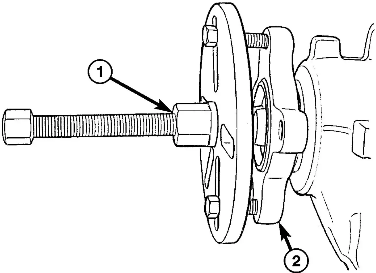
Fig. 58 FLANGE PULLER
- 1 - FLANGE PULLER
- 2 - PINION FLANGE
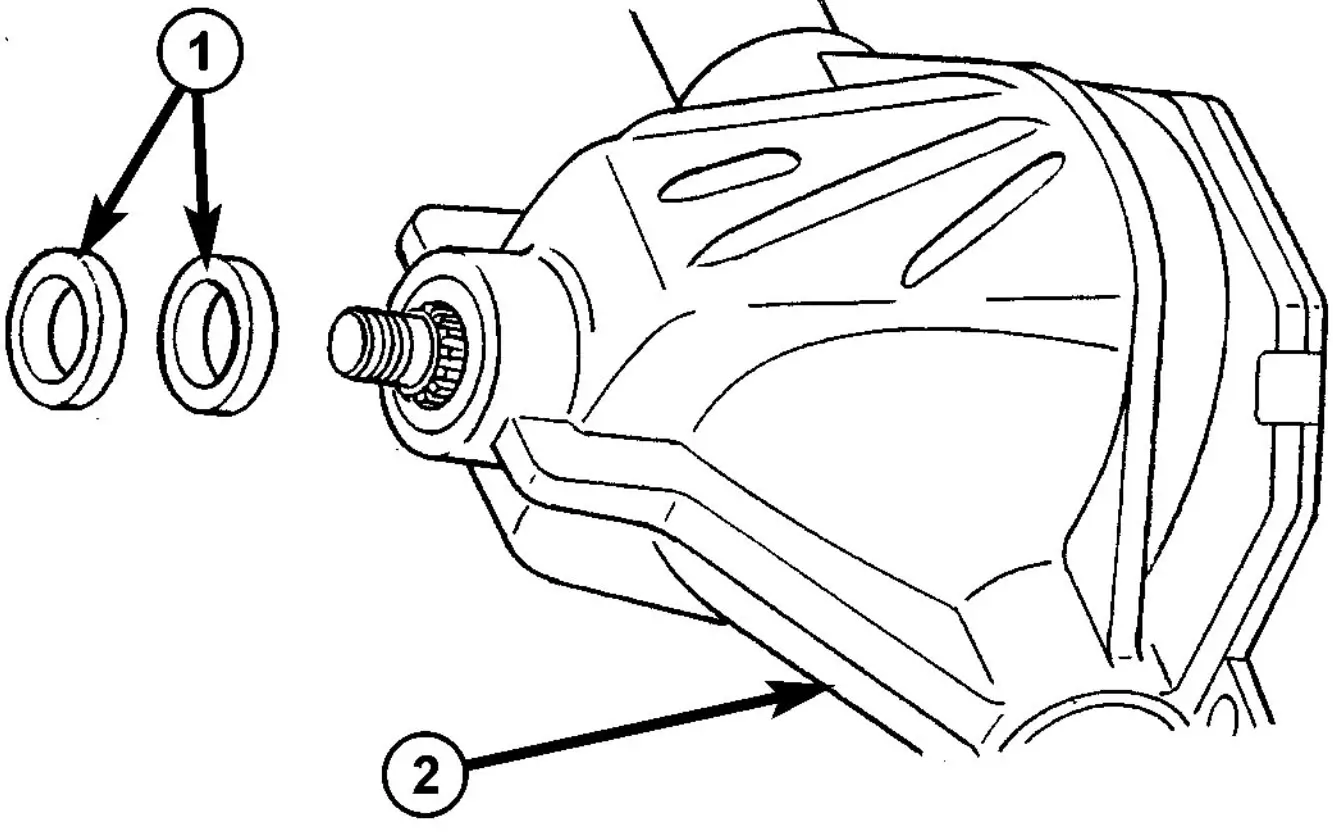
Fig. 59 PINION SEALS
- 1 - SEALS
- 2 - AXLE
(12) Remove pinion seal/seals (1) (Fig. 59).
Pinion Seal Installation
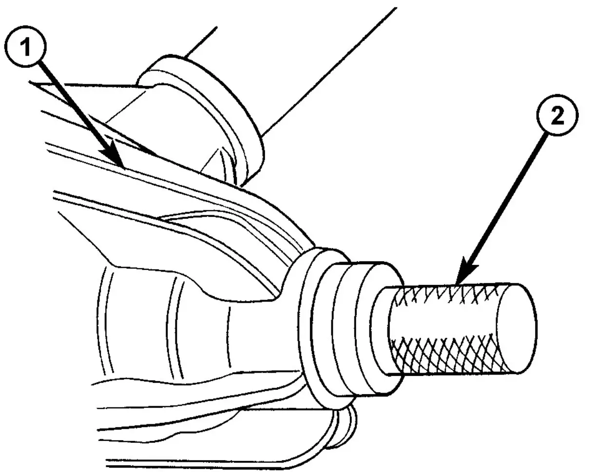
Fig. 60 PINION SEAL INSTALLER
- 1 - AXLE
- 2 - INSTALLER
(1) Pack space between dust lip and sealing lip on seal ring with multipurpose grease.
(2) On seals without a rubberized external surface, coat outer circumference with sealant.
(3) Drive new pinion seal/seals into rear axle housing as far as the stop using Installer 9276 (2) (Fig. 60).
Fig. 61 COLLARED NUT
(4) Fit coupling flange on drive pinion shaft.
(5) Hold pinion flange with Flange Wrench C-3281.
(6) Tighten collar nut to 100 N·m. (74 ft. lbs.).
(7) Using a dial indicator check free play at pinion flange.
(8) Identify the position of the pinion to the nut twelve points and mark pinion and nut.
(9) Turn nut pinion nut 30° (one twelve points). Then rotate pinion thirty times.
(10) Measure torque to rotate. The torque to rotate must be 0.1–0.2 N·m (0.9–1.7 in. lbs.) higher than recorded torque.
(11) Cut the collar of the collared nut (Fig. 61).
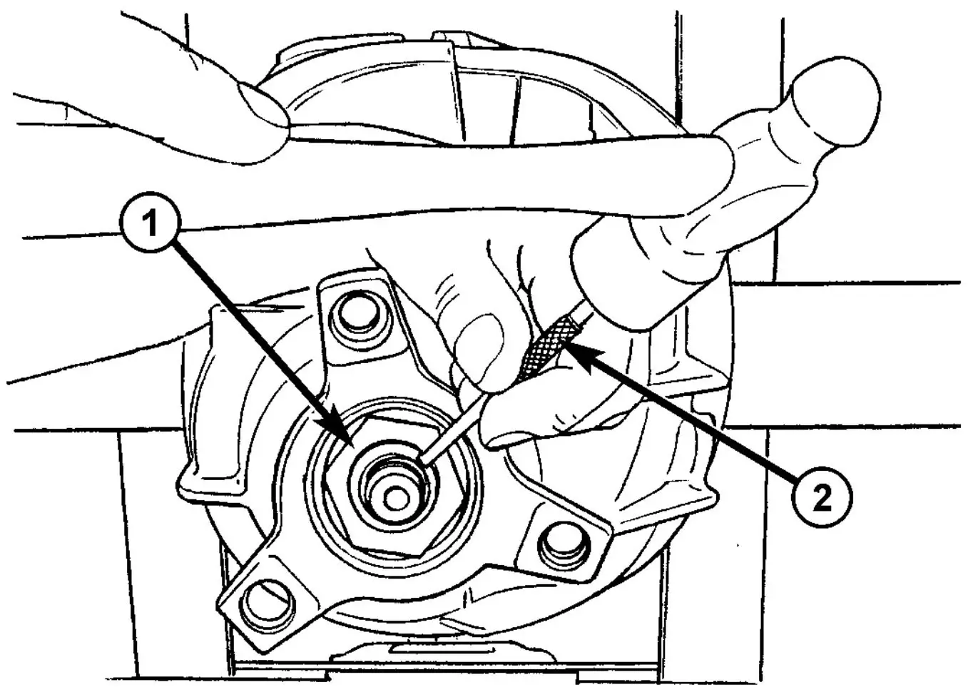
Fig. 62 BEND COLLAR OF NUT
- 1 - COLLARED NUT
- 2 - DRIFT
(12) Bend collar nut (1), so it touches the wall of the slot in the pinion shaft (Fig. 62).
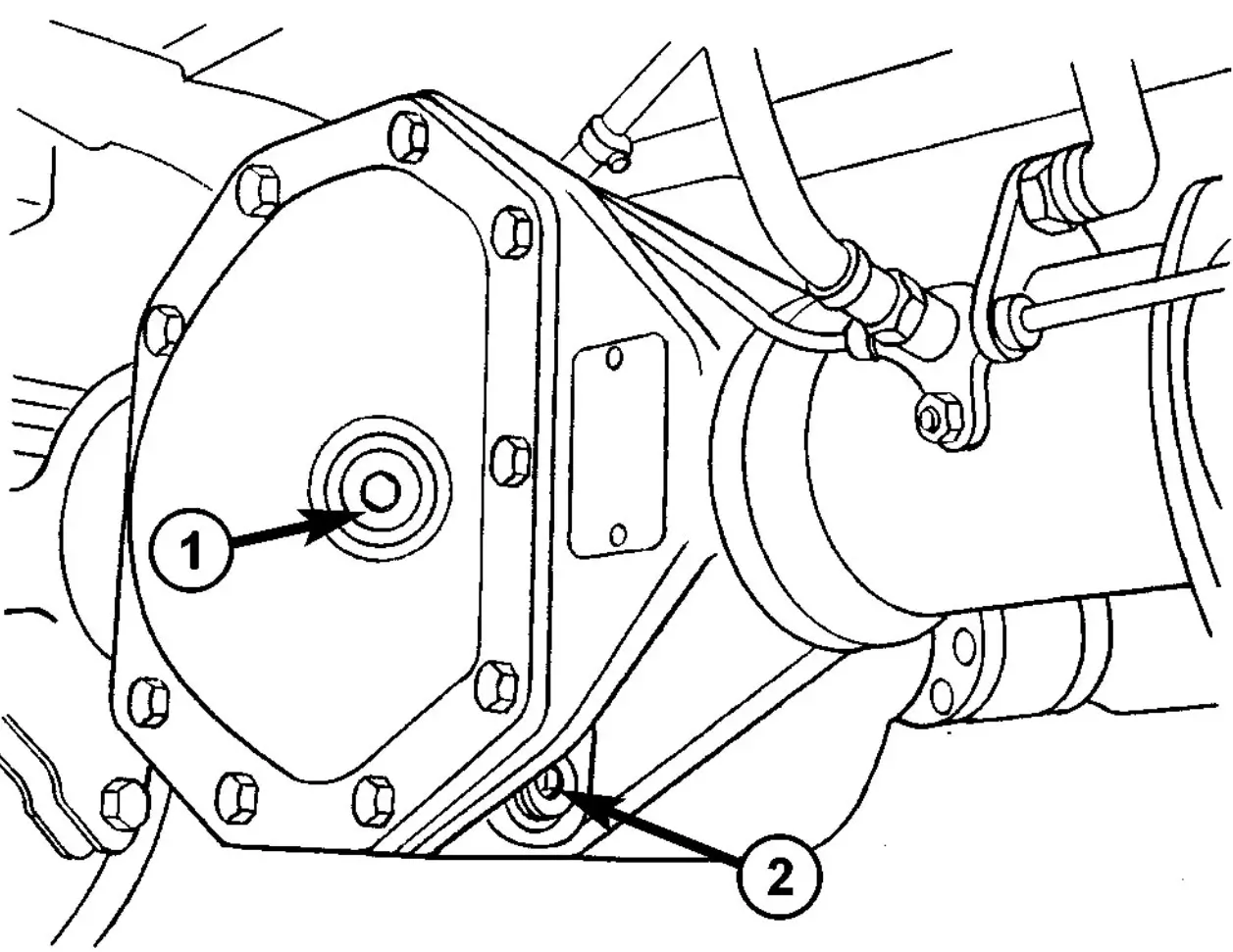
Fig. 63 FILL PLUG
- 1 - FILL PLUG
- 2 - DRAIN PLUG
(13) Connect propeller shaft to pinion flange.
(14) Pour in oil up to bottom edge of oil filler hole (1) (Fig. 63).
(15) Screw in oil filler plug (1) and tighten to 100 N·m (74 ft. lbs.).
(16) Install wheels at rear axle.
(17) Operate brake pedal several times until brake pads contact brake discs (brake pressure built up).
(18) Attach rear brake cables if removed and adjust parking brake.
Pinion Ring Gear Removal
(1) Remove differential from housing.
(2) Place differential case in a vise with soft metal jaw.
(3) Remove ring gear bolts from the differential case.
(4) Drive ring gear off the differential case with a dead-blow hammer (Fig. 64).
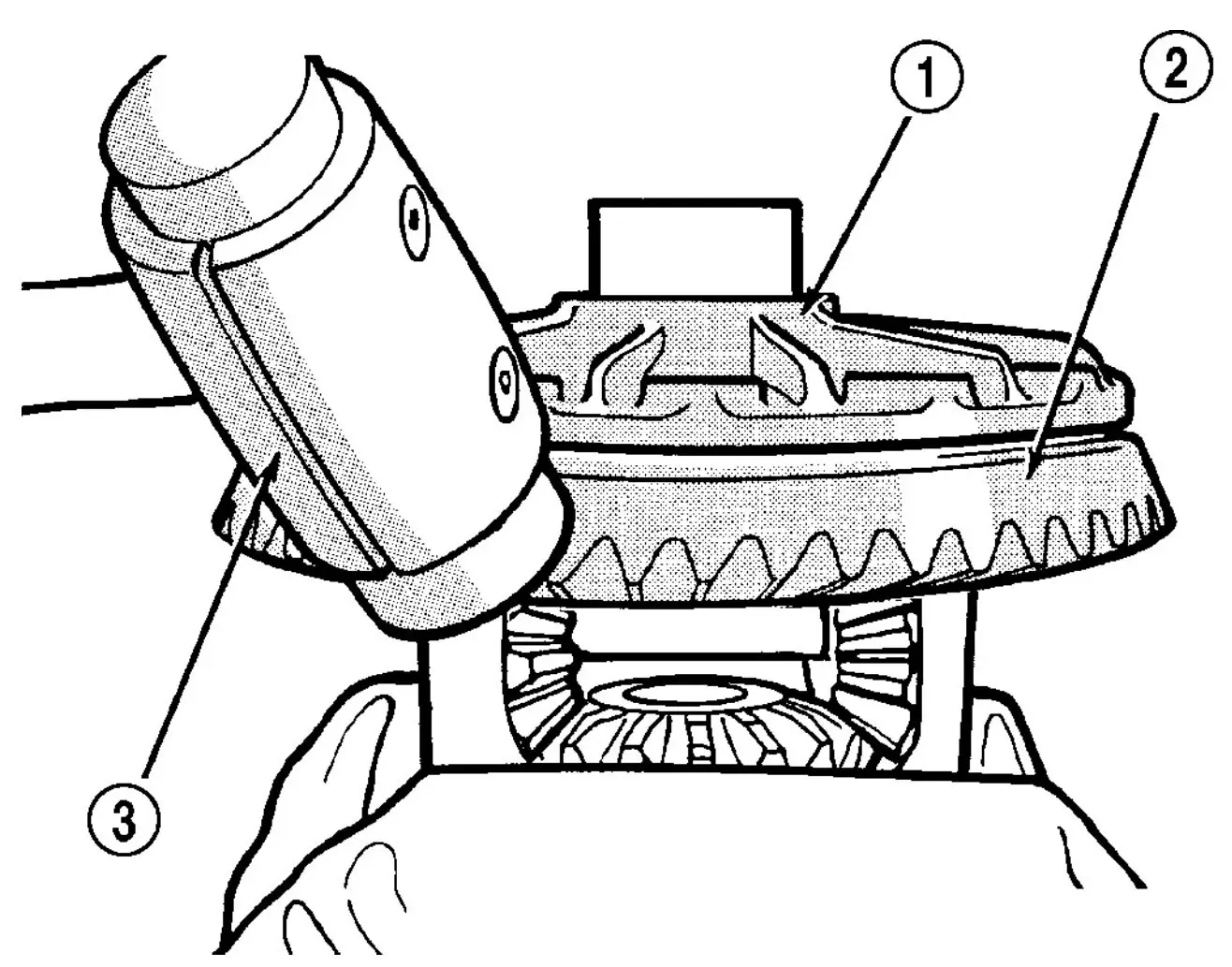
Fig. 64 RING GEAR
- 1 - CASE
- 2 - RING GEAR
- 3 - DEAD-BLOW HAMMER
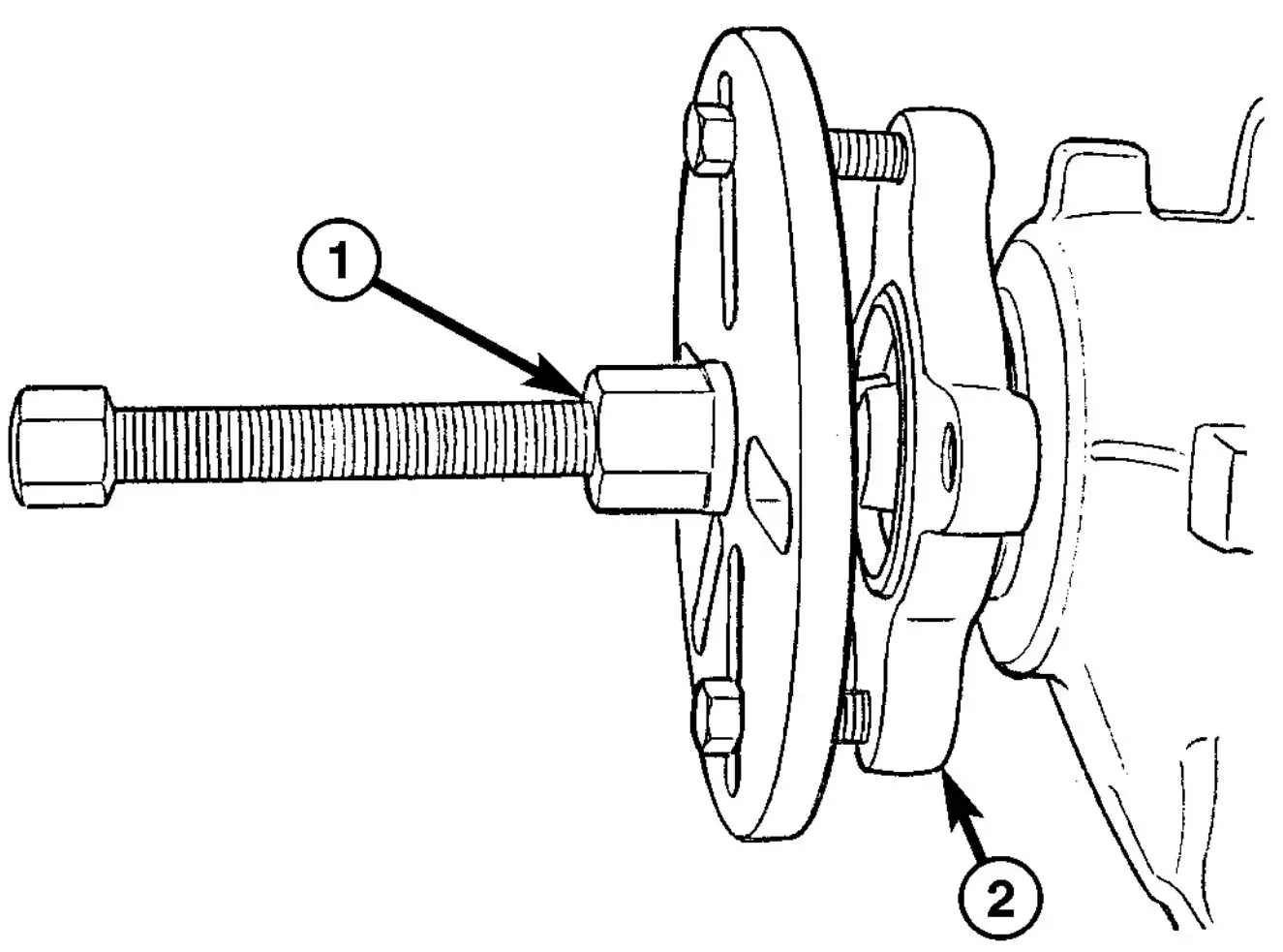
Fig. 65 FLANGE PULLER
- 1 - FLANGE PULLER
- 2 - PINION FLANGE
(8) Remove pinion gear from housing with a deadblow hammer.
(9) Remove pinion shaft seal with a seal pick.
(10) Remove front pinion bearing.
(11) Remove front pinion bearing cup with Remover D-103 and Handle C-4171.
(12) Remove rear pinion bearing cup with Remover 9084 and Handle C-4171.
(13) Remove pinion depth shim from rear pinion bearing cup bore.
(14) Remove collapsible spacer (Fig. 66).
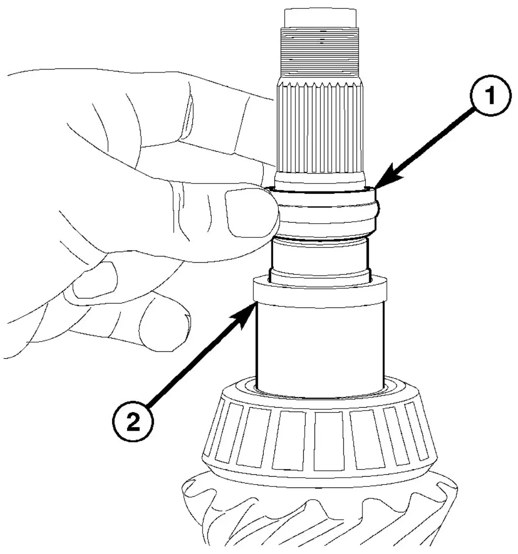
Fig. 66 COLLAPSIBLE SPACER
- 1 - COLLAPSIBLE SPACER
- 2 - SPACER
(15) Remove spacer from a pinion shaft (Fig. 67).
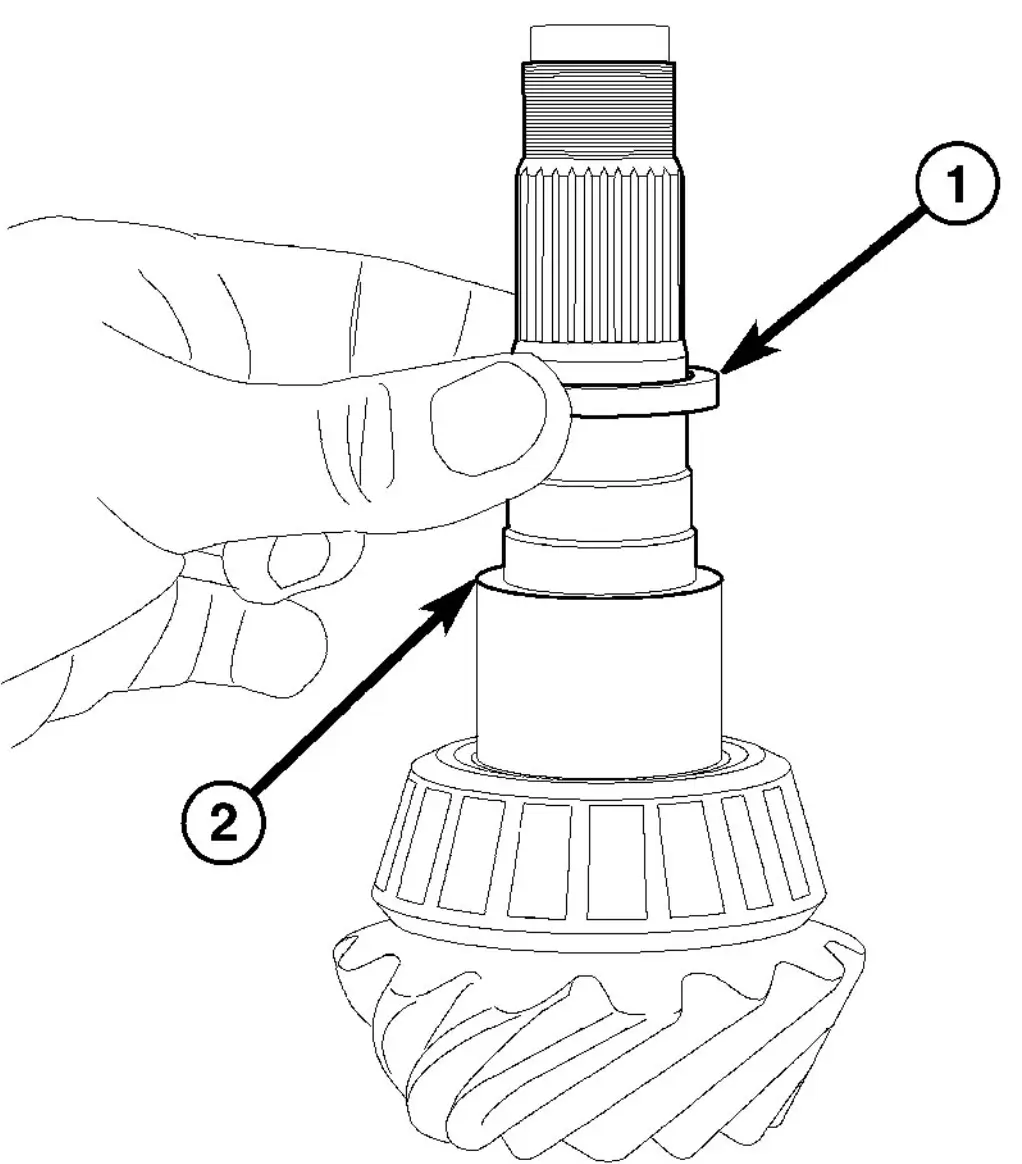
Fig. 67 SPACER
- 1 - SPACER
- 2 - PINION SHAFT
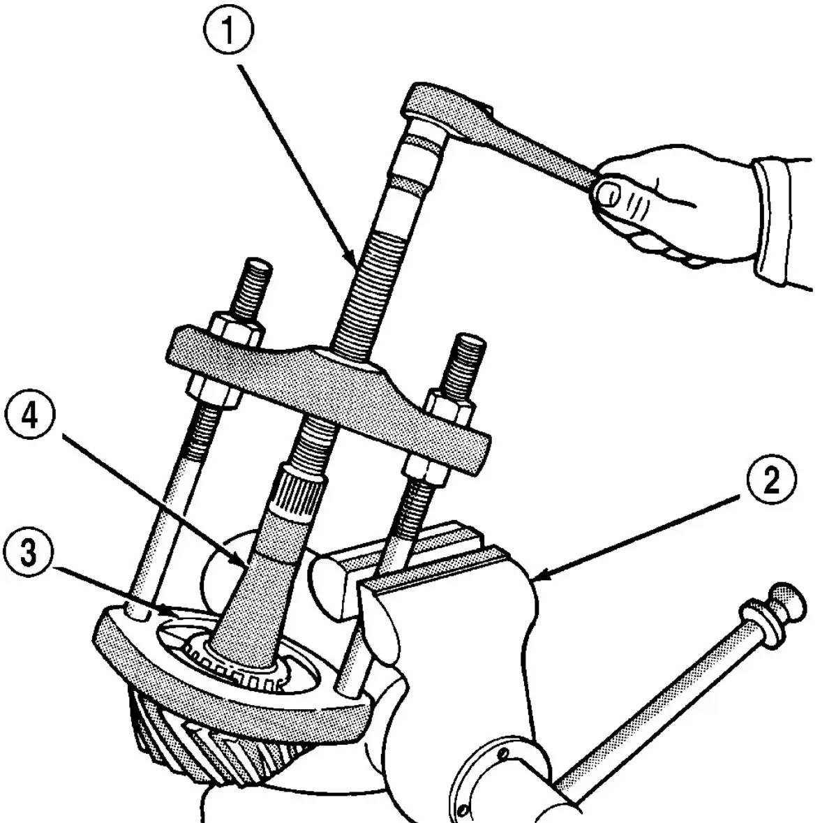
Fig. 68 Rear Bearing Removal
- 1 - PULLER
- 2 - VISE
- 3 - ADAPTERS
- 4 - DRIVE PINION GEAR SHAFT
Pinion Ring Gear Installation
(1) Apply Mopar Door Ease or equivalent lubricant to the outside surface of bearing cups.
(2) Install pinion depth shim in rear pinion bearing cup bore.
(3) Install rear pinion bearing cup with Installer C-4310 and Driver Handle C-4171.
(4) Install front pinion bearing cup with Installer 8617 and Handle C-4171.
(5) Install rear bearing on pinion with Installer MB-998805 and a press (Fig. 69).
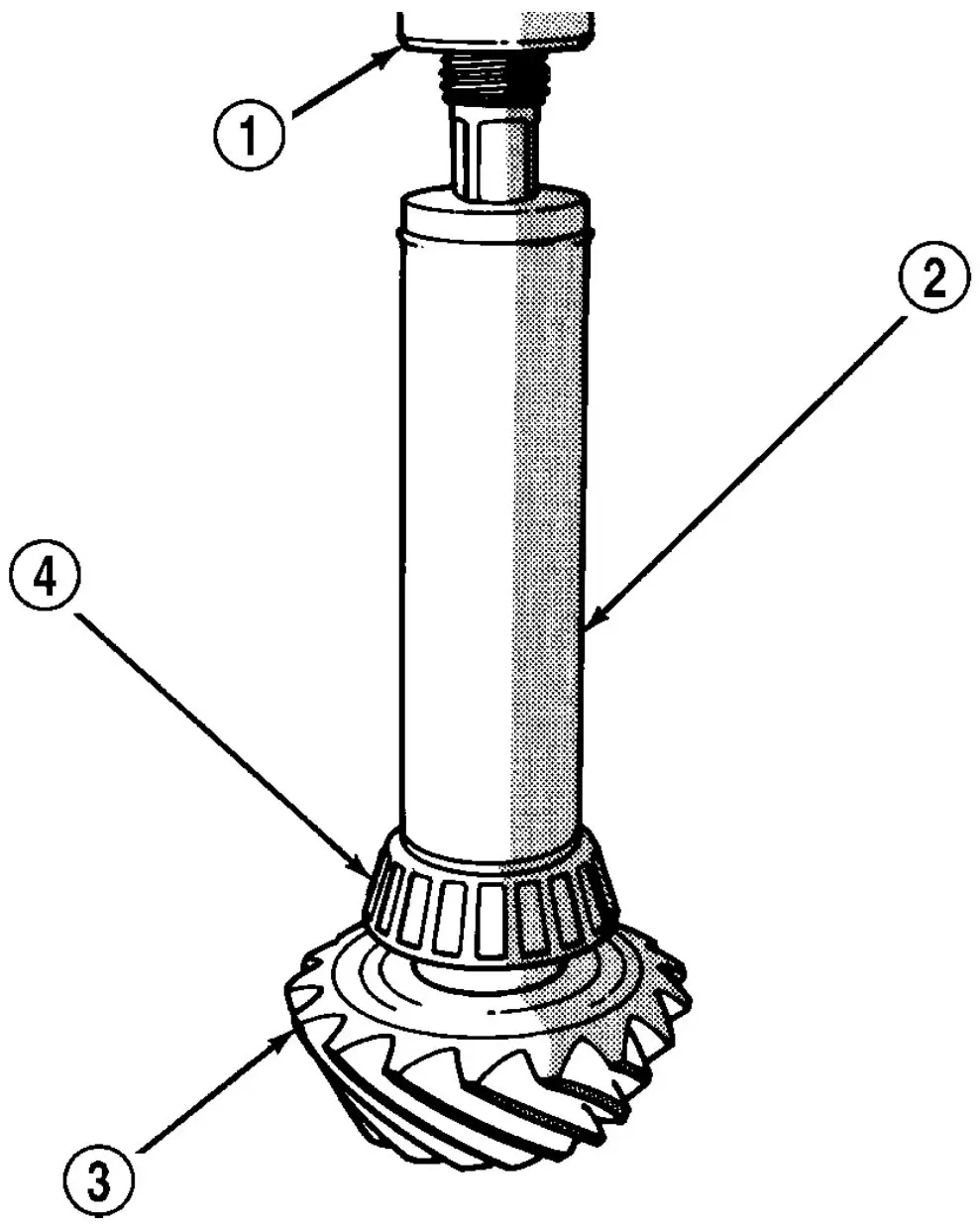
Fig. 69 REAR BEARING INSTALLATION
- 1 - PRESS
- 2 - INSTALLER
- 3 - DRIVE PINION GEAR
- 4 - REAR PINION BEARING
(6) Install pinion spacer on a pinion shaft (Fig. 70).
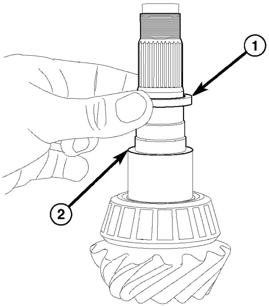
Fig. 70 SPACER
- 1 - SPACER
- 2 - PINION SHAFT
(7) Install new collapsible preload spacer on a pinion shaft (Fig. 71) and install pinion gear into the housing.
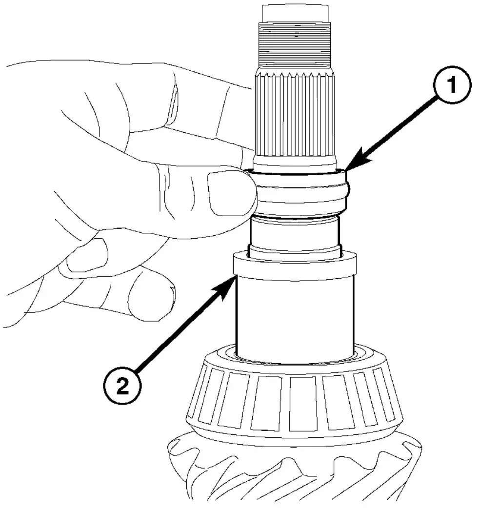
Fig. 71 COLLAPSIBLE SPACER
- 1 - COLLAPSIBLE SPACER
- 2 - SPACER
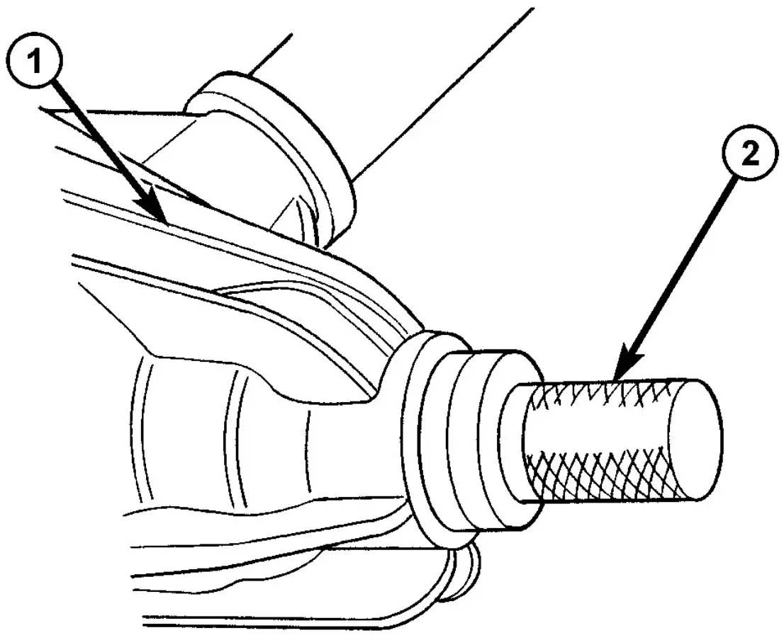
Fig. 72 PINION SEAL INSTALLER
- 1 - AXLE
- 2 - INSTALLER
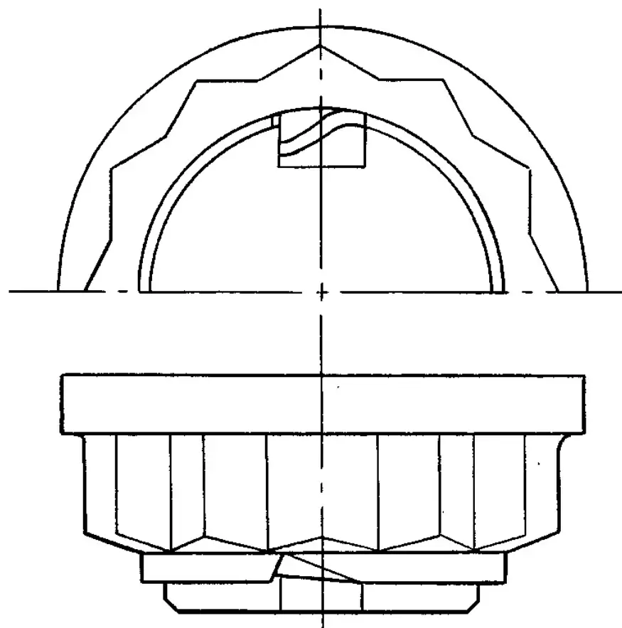
Fig. 73 COLLARED NUT
(14) Bend collar so it touches the wall of the slot in the pinion shaft (Fig. 74).
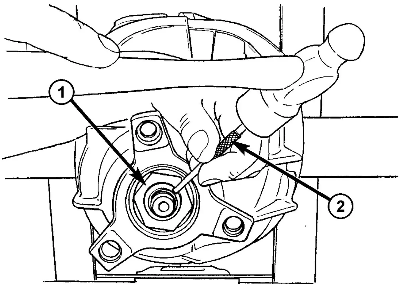
Fig. 74 BEND COLLAR OF NUT
- 1 - COLLARED NUT
- 2 - DRIFT
(15) Invert differential case and start two ring gear bolts. This will provide case-to-ring gear bolthole alignment.
(16) Invert differential case in the vise and install new ring gear bolts and alternately tighten to 180 N.m (133 ft. lbs.) (Fig. 75)
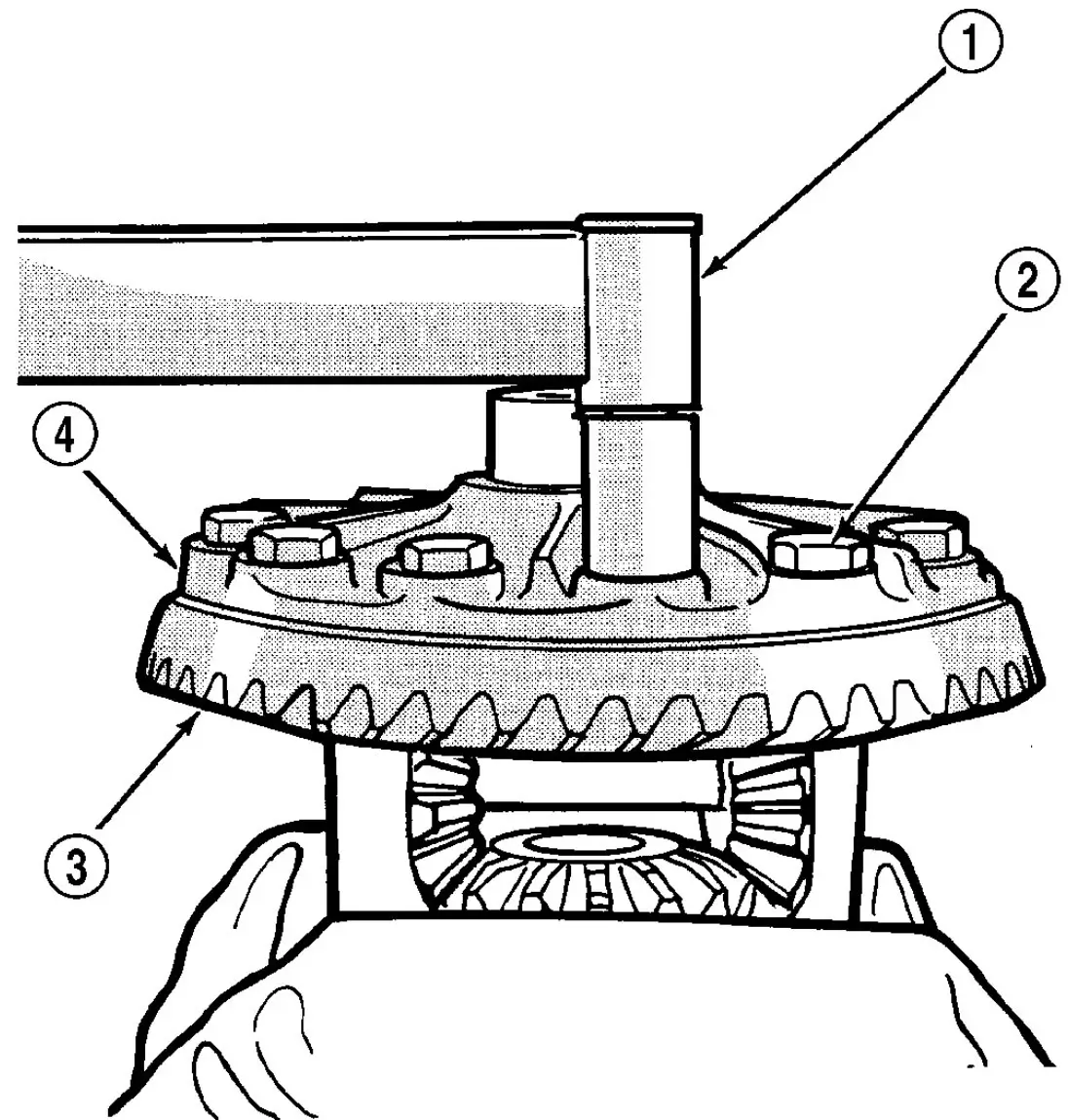
Fig. 75 RING GEAR
- 1 - TORQUE WRENCH
- 2 - RING GEAR BOLT
- 3 - RING GEAR
- 4 - CASE
(17) Install differential in axle housing and verify gear mesh and contact pattern.