T1N Sprinter Differential & Driveline - Drive Shaft
Torque Chart
| DESCRIPTION | Nm | Ft. Lbs. | In. Lbs. |
|---|---|---|---|
| Drive shaft to transmission bolt | 70 | 52 | --- |
| Drive shaft to axle bolt | 70 | 52 | --- |
| Retaining bracket to frame floor bolt | 100 | 74 | --- |
| Center Bearing support to frame floor bolt | 95 | 70 | --- |
| Center Bearing to support nut | 105 | 77 | --- |
DIAGNOSIS AND TESTING - Drive shaft Vibration
Out-of-round tires or wheels that are out of balance, will cause a low frequency vibration.
Driveline vibration can be from loose or damaged engine mounts.
Drive shaft vibration increases with vehicle speed. A vibration within a specific speed is not usually caused by a out of balanced drive shaft. Worn universal joints or an incorrect drive shaft angle, usually cause such a vibration.
DRIVELINE VIBRATION DIAGNOSIS
| Condition | Possible Causes | Correction |
|---|---|---|
| Drive shaft Noise |
|
|
| Universal Joint Noise |
|
|
Drive Shaft Balance
If a drive shaft is suspected of being out of balance, verify with the following procedure:
- Place vehicle in neutral
- Raise and support the vehicle by the axles as level as possible.
- Clean all foreign material from drive shaft and universal joints.
- Inspect drive shaft for missing balance weights, broken welds, and bent areas.
Note: If drive shaft is bent, it must be replaced.
- Inspect universal joints for wear, properly installed and correct alignment with the shaft.
- Check universal joint clamp screws torque.
- Remove wheels and tires. Install wheel lug nuts to retain the brake drums/rotors.
- Mark and number drive shaft six inches from the pinion yoke end at four positions 90° apart.
- Run and accelerate the vehicle until vibration occurs. Note intensity and speed the vibration occurred. Stop the engine.
- Install a screw clamp at position 1 (Fig. 1).
- Start the engine and re-check for vibration. If little or no change in vibration is evident, move clamp to the next positions and repeat vibration test.
Note: If there is no difference in vibration at the other positions, the vibration may not be coming from the drive shaft.
- If vibration decreased, install a second clamp (Fig. 2) and repeat vibration test.
- If additional clamp causes additional vibration, separate clamps 1/2 inch above and below the mark. Repeat the vibration test (Fig. 3).
- Increase the distance between clamps and repeat test until vibration is at the lowest level. Bend the slack end of the clamps so the screws will not loosen.
- If vibration remains unacceptable, preform the procedure to the front end of the drive shaft.
- Install the wheel and tires. Lower the vehicle.
Drive Shaft Runout Specifications
| Front of Shaft | 0.020 in. (0.50 mm) |
| Center of Shaft | 0.025 in. (0.63 mm) |
| Rear of Shaft | 0.020 in. (0.50 mm) |
|
Note: Measure front/rear runout approximately 76 mm (3 in.) from the weld seam at each end of the shaft tube for tube lengths over 30 inches. For tube
lengths under 30 inches, the maximum allowed runout is 0.50 mm (0.020 in.) for the full length of the tube.
|
|
Drive Shaft Angle
This procedure applies the front and rear drive shafts.
- Place vehicle in neutral
- Raise and support vehicle at the axles as level as possible.
- Remove universal joint snap rings if equipped, so Inclinometer 7663 base sits flat.
- Rotate shaft until transmission case output yoke bearing is facing downward.
Note: Always make measurements from front to rear and from the same side of the vehicle.
- Place Inclinometer 7663 on yoke bearing (A) parallel to the shaft. Center bubble in sight glass and record measurement. measurement will give you the transmission yoke Output Angle (A).
- Rotate drive shaft 90 degrees and place inclinometer on yoke bearing parallel to the shaft. Center bubble in sight glass and record measurement. This measurement can also be taken at the rear end of the shaft. This measurement will give you the drive Shaft Angle (C).
- Rotate drive shaft 90 degrees and place inclinometer on companion flange yoke bearing parallel to the shaft. Center bubble in sight glass and record measurement. This measurement will give you the Pinion Flange Input Angle (B).
- Subtract a smaller figure from larger (C minus A) to get Transmission Output Operating Angle.
- Subtract a smaller figure from larger (C minus B) to get axle Input Operating Angle. Refer to rules and example in (Fig. 4) for additional information.
Rules
|
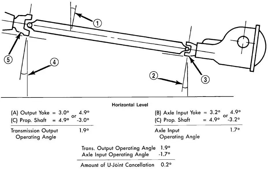
Fig. 4 UNIVERSAL JOINT ANGLE EXAMPLE
- 4.9° Angle (C)
- 3.2° Angle (B
- Input Yoke
- 3.0° Angle (A)
- Output Yoke
TWO / THREE - PIECE DRIVE SHAFT Angle
The procedure to measure the drive shaft angles involved with a two/three-piece (Fig. 5) drive shaft is the same as those for a one-piece drive shaft.
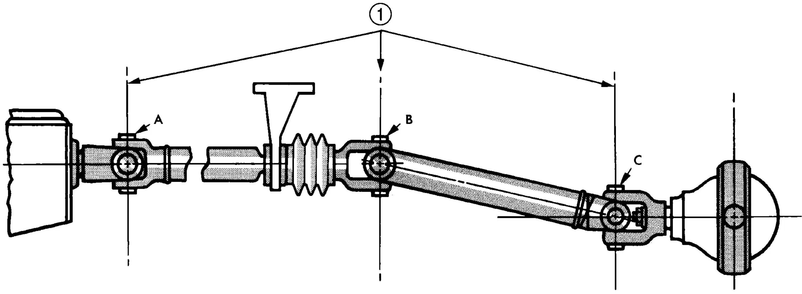
Fig. 5 UNIVERSAL JOINT ANGLE
- YOKES MUST BE IN SAME PLAN
Special Tools
Special Tool Cross-reference Chart
| Mb Tool # | Miller Tool # | Description | Image |
|---|---|---|---|
| N/A | 938 | BRIGE | 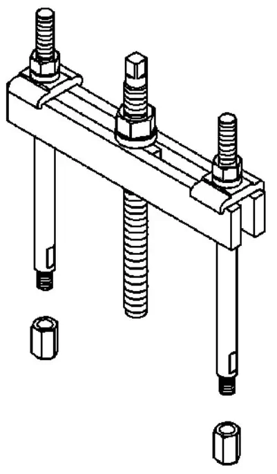
|
| N/A | 1130 | SPLITTER | 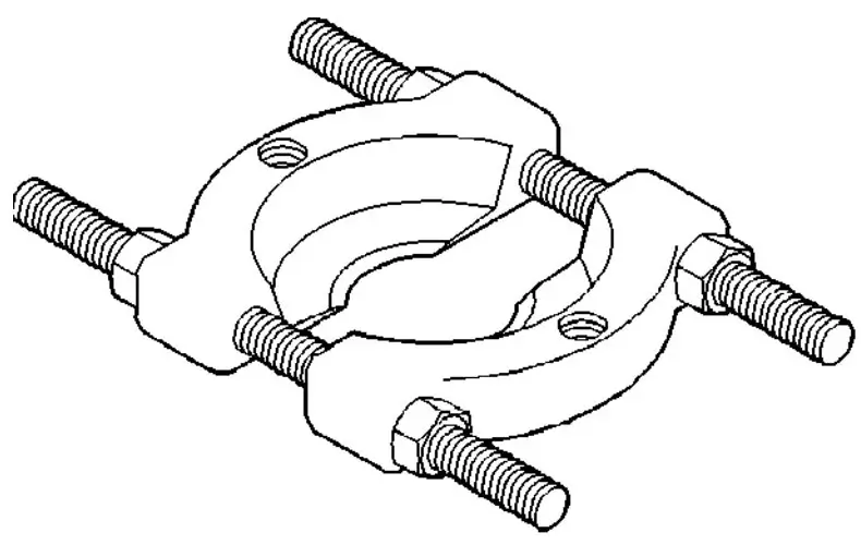 |
| 387 589 05 15 00 | 9275 | INSTALLER | 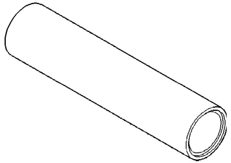 |
| N/A | 7663 | INCLINOMETER | 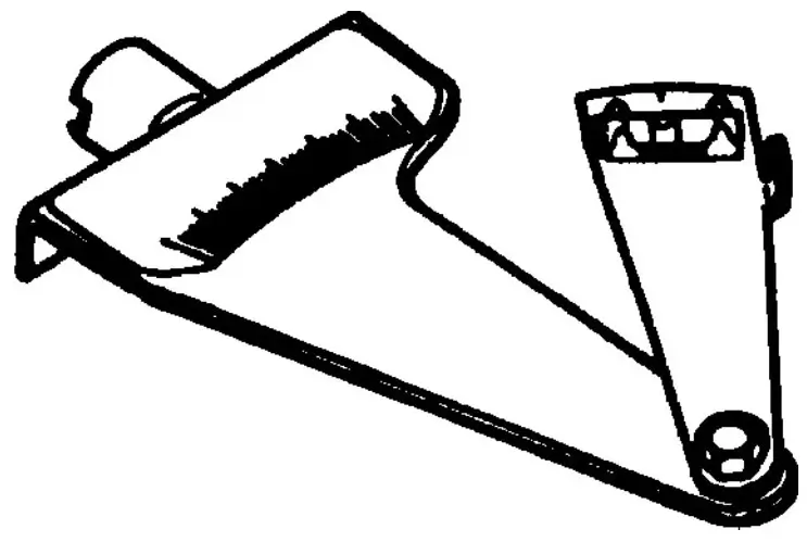 |
Drive Shaft Removal
- Secure vehicle to prevent it from rolling.
- Make installing reference marks on drive shaft (Fig. 6) and (Fig. 7).
- Remove retaining bracket bolts (Fig. 8) and (Fig. 9).
- Remove drive shaft bolts from rear axle and transmission at the flange.
- Remove drive shaft intermediate bearing nuts from retaining bracket and bracket for brake cable.
Note: The brake cable bracket is only installed in vehicles with wheelbase 3550 mm
- Remove shaft from the vehicle.

Fig. 6 ALIGNMENT MARKS
- ALIGNMENT MARK
- BOOT
- ALIGNMENT MARK
- CENTER BEARING
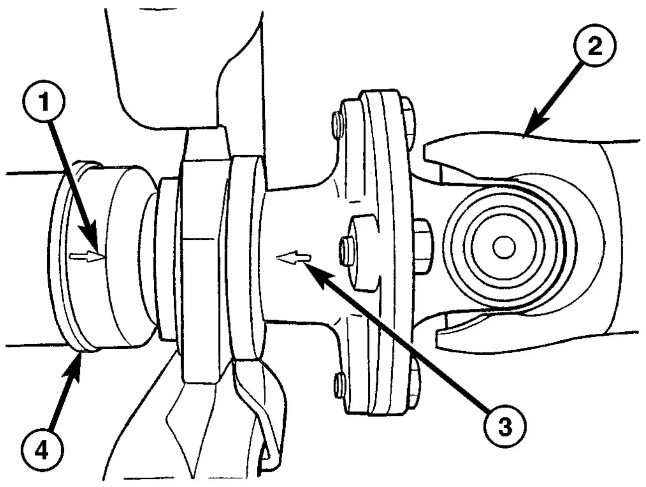
Fig. 7 ALIGNMENT MARKS 3 PIECE SHAFT
- REFERNCE MARK
- CENTER SHAFT
- REFERENCE MARK
- REAR SHAFT
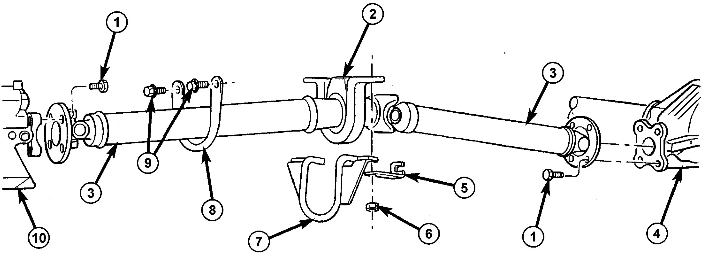
Fig. 8 2 PIECE DRIVE SHAFT
- FLANGE BOLT
- BEARING
- DRIVE SHAFT
- REAR AXLE
- CABLE BRACKET
- NUT
- BRACKET
- RETAINING BRACKET
- COLLARED BOLT
- TRANSMISSION
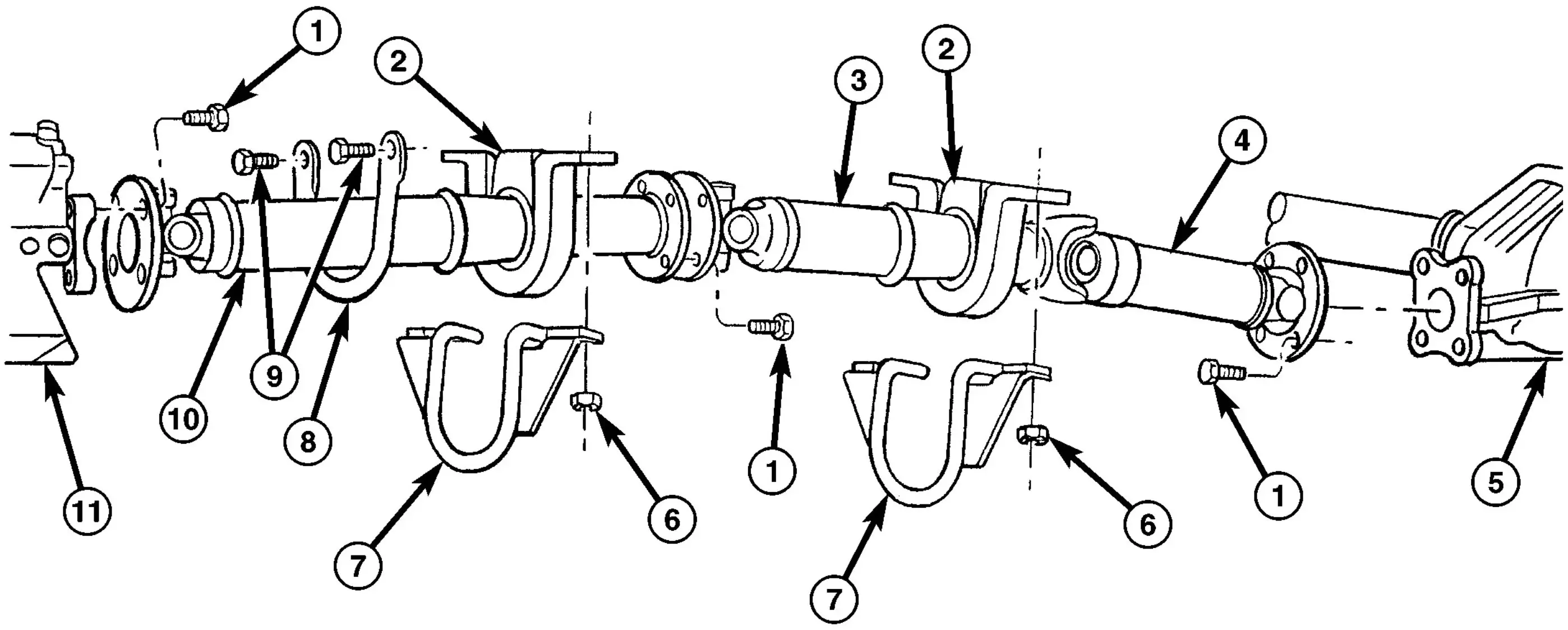
Fig. 9 3 PIECE DRIVE SHAFT
- FLANGE BOLT
- INTERMEDIATE BEARING
- CENTER SHAF
- REAR SHAFT
- REAR AXLE
- NUT
- BRACKET
- RETAINING BRACKET
- BOLT
- FRONT SHAFT
- TRANSMISSION
Drive Shaft Installation
- Install drive shaft intermediate bearing/ bearings to support and tighten nuts to 105 N·m (77 ft. lbs.).
- Install drive shaft intermediate bearing support/supports to a frame floor and tighten bolts to 95 N·m (70 ft. lbs.).
- Install drive shaft intermediate bearing with retaining bracket and bracket for brake cable.
Note: The bracket is only installed on vehicles with wheelbase 3550 mm.
- Install drive shaft to rear axle and transmission flange with installation marks are aligned. Tighten bolts to 70 N·m (66 ft. lbs.).
- Install retaining bracket and tighten bolts to 100 N·m (74 ft. lbs.).
Center Bearing Removal
- Remove drive shaft.
- Mark shafts for installation alignment (Fig. 10).
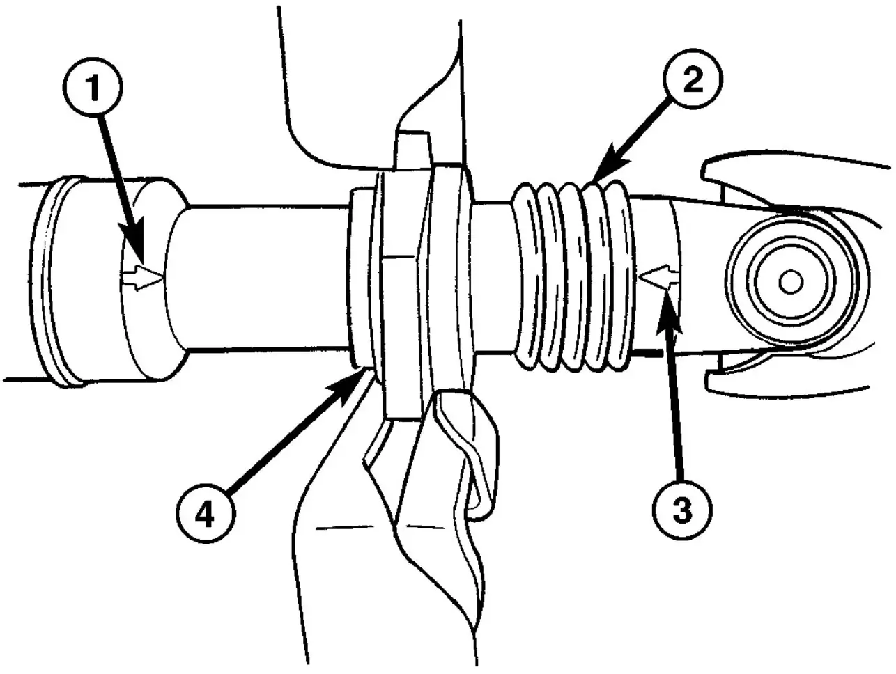
Fig. 10 ALIGNMENT MARKS
- ALIGNMENT MARK
- BOOT
- ALIGNMENT MARK
- CENTER BEARING
- Loosen both collar clamps (Fig. 11).
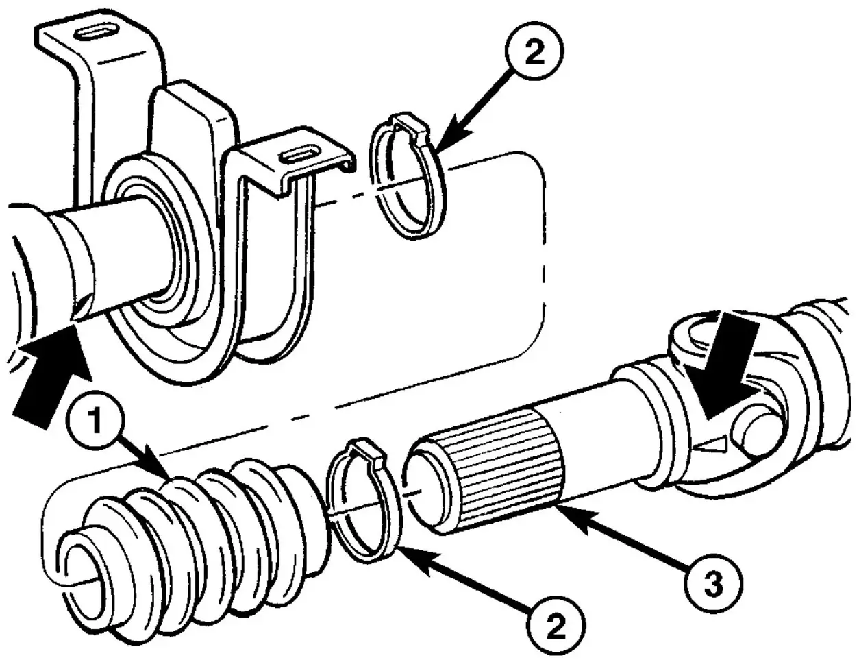
Fig. 11 BOOT
- BOOT
- CLAMP
- SHAFT
- Pull apart drive shaft.
- Remove snap-ring (Fig. 12)
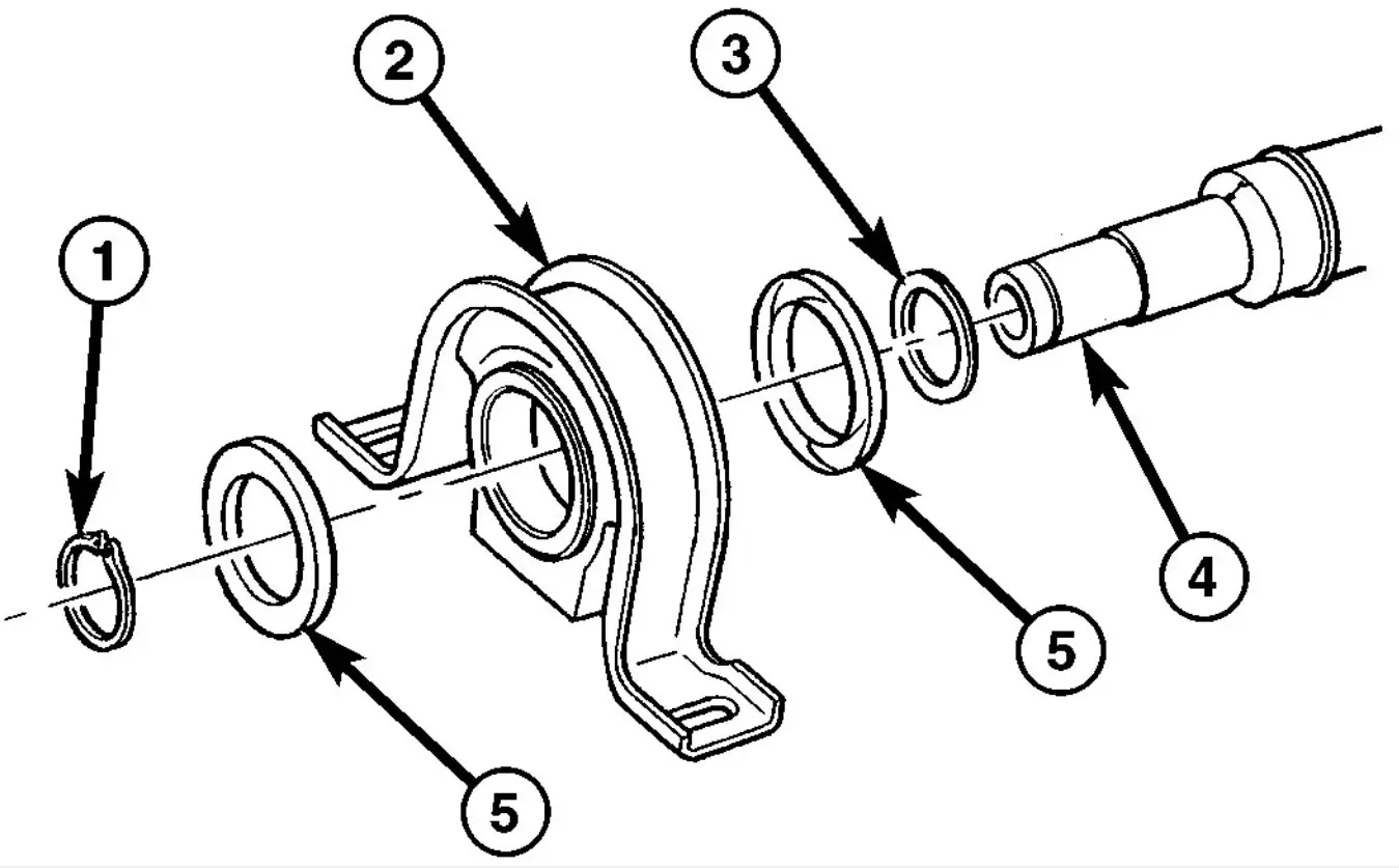
Fig. 12 CENTER BEARING
- SNAP-RING
- CENTER BEARING
- WASHER
- SHAFT
- PROTECTIVE CAP
Note: If center bearing is equipped with a round flange remove bolt from the middle of the flange. - Pull off center bearing with a Bearing Splitter 1130 and Bridge 938, with a plug on the end of the shaft (Fig. 13).
Note: The bearing splitter must be positioned behind the thrust washer of the bearing.
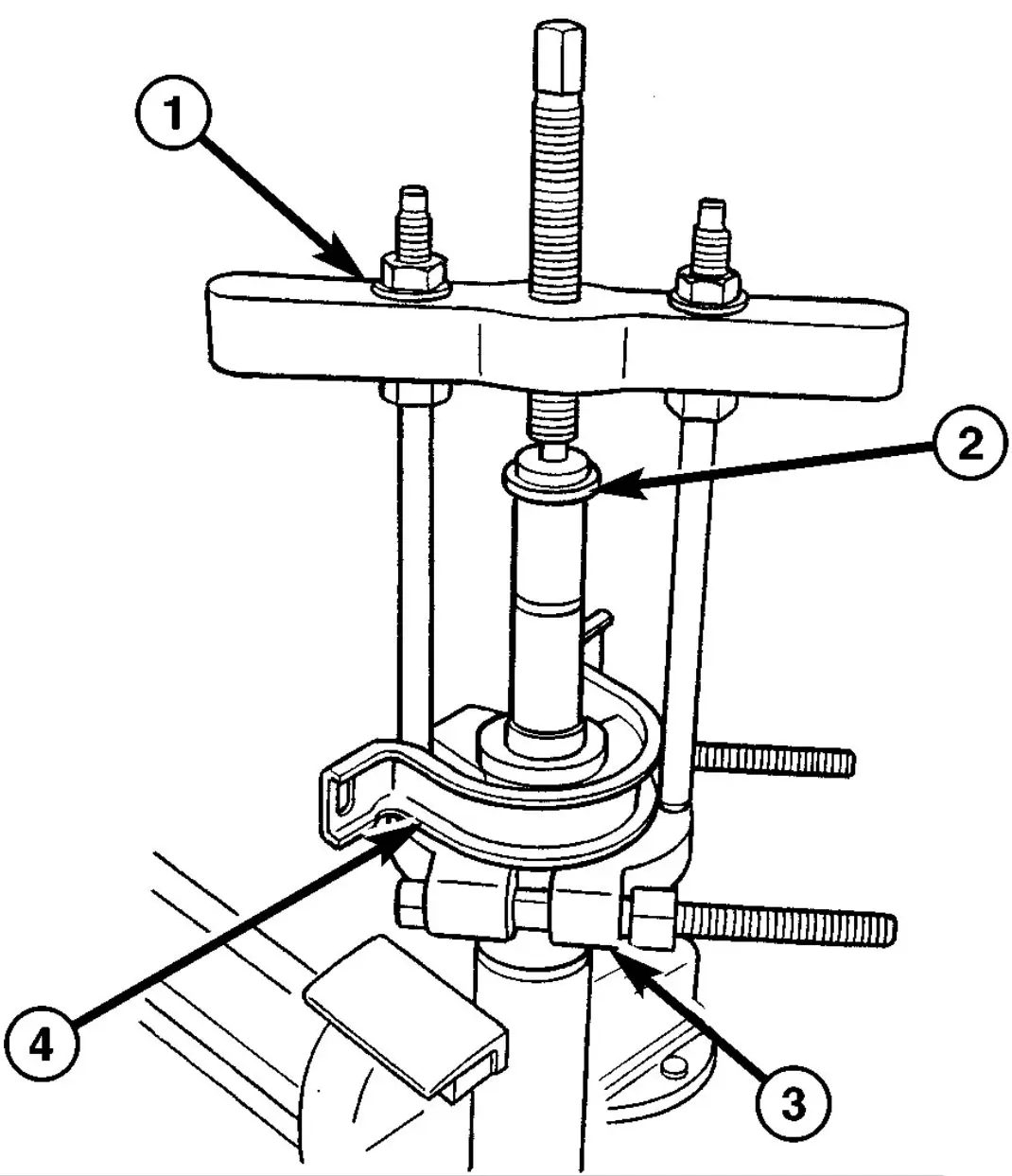
Fig. 13 CENTER BEARING REMOVAL
- BRIDGE
- PLUG
- BEARING SPLITTER
- CENTER BEARING
Center Bearing Installation
- Press center bearing on drive shaft with protective caps and washer with Installer 9275 (Fig. 14).
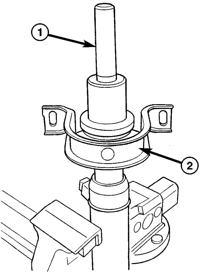
Fig. 14 CENTER BEARING INSTALLATION
- INSTALLER
- CENTER BEARING
Note: If center bearing is equipped with a round flange install new bolt in middle of the flange and tighten to 95 N·m (70 ft. bls.). - Install snap-ring
- Coat drive shaft spline with universal grease.
- Push rubber boot onto drive shaft.
- Push together drive shaft. Pay attention to alignment markings for installation position.
- Ensure rubber seal is correctly installed and attach new collar clamps.
- Install drive shaft.